Power factor correction capacitors serve a specific and important purpose in electrical systems—they reduce wasted electrical current and improve overall system efficiency. The concept sounds simple enough when stated that way, but the actual mechanics involve some interesting electrical behavior that’s worth understanding.
Most facility managers and building owners encounter power factor issues without fully grasping what’s happening. Utility bills show penalty charges. Electricians mention something about reactive power. Equipment runs warm. The electrical system seems to work harder than it should. Installing a power factor correction capacitor addresses these symptoms by tackling the underlying electrical inefficiency directly.
Table of Contents
The Core Function of a Power Factor Correction Capacitor
Compensating for Inductive Loads
Industrial and commercial facilities contain lots of inductive equipment. Motors are everywhere—in HVAC systems, pumps, conveyors, compressors, elevators, fans. Transformers sit throughout the electrical distribution system. Older fluorescent lighting with magnetic ballasts adds more inductive load. All this equipment shares a common characteristic: it causes current to lag behind voltage.
This lag creates what engineers call reactive power. The current still flows through wires, still passes through transformers, still gets metered by utilities—but it doesn’t actually perform useful work. It’s electricity that sloshes back and forth in the system rather than powering equipment.
A power factor correction capacitor does the opposite of inductive loads. Instead of causing current to lag, capacitors cause current to lead voltage. When you connect capacitors to a system with inductive loads, the leading current from capacitors and the lagging current from inductors partially cancel out. The net effect is reduced reactive power and improved power factor.
The Practical Result
With properly sized correction capacitors installed, several things happen:
- Total current drawn from the utility decreases
- Power factor readings improve toward unity (1.0)
- System losses throughout the facility decrease
- Voltage stability improves
- Available capacity in existing infrastructure increases
These aren’t theoretical possibilities—they’re predictable, measurable outcomes that occur when correction is done properly.
Why Power Factor Correction Capacitor Installation Matters
Financial Impact
The money side of power factor correction tends to drive most decisions, honestly. Utilities structure rates in ways that penalize poor power factor, sometimes heavily:
- Direct power factor penalty charges when PF falls below threshold (often 0.90)
- Higher demand charges based on kVA rather than kW
- Increased energy costs from system losses
- Potential rate class changes that affect overall pricing
The exact financial impact varies enormously depending on utility rate structures, facility size, and how poor the existing power factor is. Some facilities see modest savings. Others recover installation costs within months due to eliminated penalties.
。
System Capacity Benefits
Beyond direct costs, power factor correction capacitor systems free up electrical capacity. Consider a facility operating at 0.70 power factor. Correcting to 0.95 reduces current by about 26%. That’s significant.
Transformers rated for certain kVA can serve more actual load. Cables that were running warm have more headroom. Circuit breakers operate further from their limits. A facility bumping against infrastructure constraints might suddenly have room for expansion—without upgrading a single piece of electrical equipment.
| Power Factor | Current Draw (relative) | Available Capacity | System Losses |
|---|---|---|---|
| 0.70 | 143% | 70% | High |
| 0.80 | 125% | 80% | Moderate-High |
| 0.85 | 118% | 85% | Moderate |
| 0.90 | 111% | 90% | Moderate-Low |
| 0.95 | 105% | 95% | Low |
| 1.00 | 100% | 100% | Minimum |
Types of Power Factor Correction Capacitor Systems
Fixed Capacitor Banks
The simplest approach uses capacitors that remain permanently connected. They provide constant correction regardless of load conditions. This works well when:
- Loads remain relatively constant throughout operation
- Minimum load still requires substantial correction
- Cost minimization is a priority
- System simplicity is valued
Fixed installations cost less and have fewer components that can fail. The tradeoff is inflexibility—they can’t adjust as loads change.
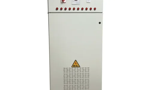
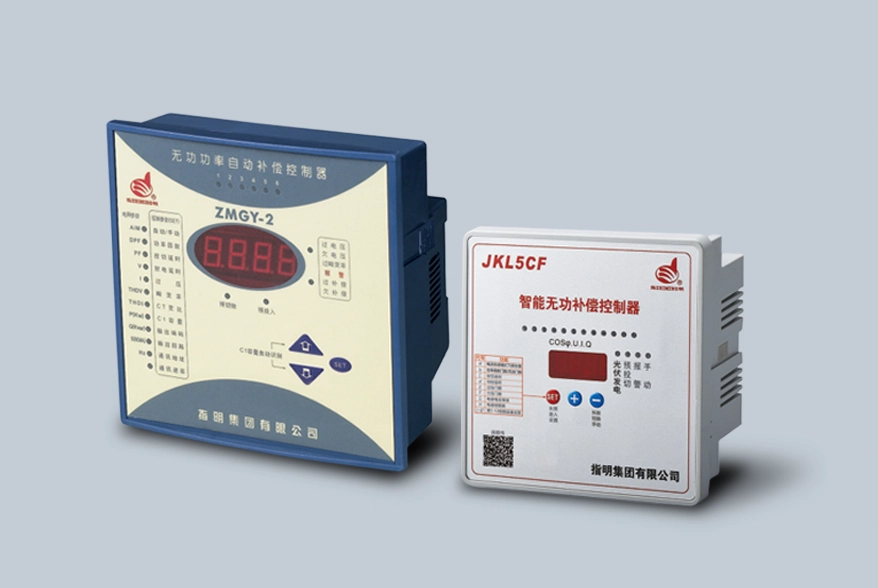
Automatic Capacitor Banks
Variable loads require more sophisticated solutions. Automatic power factor correction capacitor banks use controllers that monitor power factor continuously and switch capacitor stages in and out as needed.
Key features include:
- Real-time power factor monitoring
- Multiple capacitor stages (typically 6-12 steps)
- Automatic switching based on programmable setpoints
- Protection against overcorrection
- Communication capabilities for monitoring systems
The added complexity brings added cost, but for facilities with significantly varying loads, automatic systems prevent the overcorrection problems that fixed systems can create.
Individual Motor Correction
Sometimes capacitors mount directly at individual motors rather than in centralized banks. This approach corrects power factor right at the source, reducing current flow through the entire distribution system feeding that motor.
Individual correction works particularly well for:
- Large motors that dominate facility load
- Motors running continuously
- Situations where distribution system relief is important
- New motor installations where correction can be planned from the start
Installation Considerations for Power Factor Correction Capacitor Equipment
Sizing Requirements
Proper sizing matters enormously. Undersized installations provide partial correction at best. Oversized installations push power factor into leading territory, potentially causing overvoltage and utility penalties for leading power factor.
The sizing process involves:
- Measuring existing power factor and load characteristics
- Determining target power factor (usually 0.95)
- Calculating required kVAR compensation
- Selecting appropriate capacitor ratings
- Accounting for system voltage and frequency
Harmonic Concerns
Modern facilities often have significant harmonic distortion from variable frequency drives, LED lighting systems, computers, and other nonlinear loads. Standard power factor correction capacitor installations can interact badly with harmonics, potentially creating resonance conditions that amplify rather than reduce problems.
Facilities with substantial harmonic content may need detuned reactors in series with capacitors. These reactors shift system resonance away from common harmonic frequencies, preventing amplification issues. It adds cost but avoids potentially serious consequences.
What Happens Without Correction
Leaving poor power factor unaddressed has consequences that compound over time:
- Ongoing penalty charges that never stop
- Higher energy costs from continuous losses
- Shortened equipment life from excess heating
- Limited expansion capability
- Voltage problems affecting sensitive equipment
The situation doesn’t improve on its own. Inductive loads don’t become less inductive. If anything, adding more motors or transformers makes things worse. Power factor correction capacitor installation addresses the root cause rather than managing symptoms. If you want to know more about power factor correction capacitor, please read about What is a power factor correction capacitor.
FAQ
How long do power factor correction capacitors typically last?
Quality capacitors from reputable manufacturers generally last 10-15 years under normal operating conditions. Several factors affect lifespan—ambient temperature, voltage transients, harmonic stress, and switching frequency for automatic systems. Capacitors in harsh environments or those subjected to frequent switching may degrade faster. Regular inspection helps identify units approaching end of life before failure occurs.
Can power factor correction capacitors be installed on any electrical system?
Most industrial and commercial systems benefit from correction, but some conditions require special consideration. Systems with significant harmonic distortion need detuned designs. Very old installations may require electrical upgrades before capacitor installation. Some specialty applications have unique requirements. A qualified engineer or electrician familiar with power factor correction should evaluate specific situations before proceeding.
Do power factor correction capacitors reduce actual energy consumption?
They reduce system losses, which does decrease total energy consumption modestly. However, the primary benefit is reducing reactive power and improving power factor—not directly reducing the energy consumed by loads. A motor still uses the same power to do its work. What changes is how efficiently the electrical system delivers that power. Savings come primarily from reduced penalties, lower demand charges, and decreased system losses rather than fundamental load reduction.