Electrical systems have this persistent issue with reactive power. Motors, transformers, and other inductive loads draw current that lags behind voltage, creating inefficiencies that cost money and strain infrastructure. The solution? Capacitors — specifically, in industrial settings, the 3-phase capacitor.
But how does a 3-phase capacitor actually work? The concept seems straightforward enough on the surface. Capacitors provide leading current that offsets lagging current from inductive loads. The math works out neatly in textbooks. Real-world application, though, involves considerations that those textbooks sometimes gloss over.
Understanding the operating principles behind a 3-phase capacitor helps in selecting the right equipment, troubleshooting problems when they arise, and appreciating why these devices are so common in commercial and industrial electrical installations.
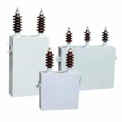
Table of Contents
Basic Principles Behind a 3-Phase Capacitor
Reactive Power and Why It Matters
Before diving into capacitor operation, the underlying problem deserves attention. Industrial facilities run motors — lots of them. Pumps, compressors, conveyors, fans. These motors are inductive loads that consume reactive power in addition to the real power that does actual work.
Reactive power doesn’t accomplish useful work directly. It flows back and forth between the source and the load, occupying conductor capacity and increasing current flow without adding to energy consumption in a productive sense. Utilities penalize customers for poor power factor because this reactive current still requires infrastructure to deliver.
A 3-phase capacitor addresses this by generating reactive power locally, at or near the load. The capacitor provides the reactive current that motors need, which means that reactive current no longer has to travel from the utility through transformers, cables, and switchgear. Losses decrease. Power factor improves. Utility bills often drop noticeably.
How Capacitors Generate Leading Current
In AC circuits, capacitors exhibit behavior opposite to inductors. Where an inductor causes current to lag voltage, a capacitor causes current to lead voltage — by 90 degrees in an ideal case, slightly less in reality due to internal losses.
When connected across an AC supply, a 3-phase capacitor draws leading current from each phase. This leading current combines with the lagging current drawn by inductive loads, and the net reactive current seen by the supply decreases. The effect is sometimes described as the capacitor “supplying” reactive power to the load, though nothing is really being supplied in the conventional sense — it’s more about local circulation of reactive energy.
The magnitude of correction depends on the capacitor’s kVAr rating. Higher kVAr means more reactive power compensation. Getting the rating right matters — undercorrection leaves money on the table, while overcorrection creates its own problems including overvoltage conditions and potential resonance issues.
3-Phase Capacitor Configurations and Connections
Delta and Star Connection Options
A 3-phase capacitor bank can be connected in either delta or star (wye) configuration. The choice affects voltage rating requirements and how the capacitors respond to unbalanced conditions or single-phase faults.
Configuration | Capacitor Voltage Rating | Typical Application | Fault Behavior |
Delta | Line-to-line voltage | Higher voltage systems | Single capacitor failure may cause overcurrent in remaining units |
Star (Wye) | Line-to-neutral voltage | Systems with neutral available | Better isolation of faulted phase |
Star with floating neutral | Line-to-neutral voltage | Systems without neutral | Requires voltage rebalancing consideration |
Many 3-phase capacitor units contain internal connections already configured by the manufacturer. Some allow field-selectable configuration. Checking the nameplate and installation manual before connecting anything is more important than it might sound — incorrect connection can destroy the capacitor or create dangerous conditions.
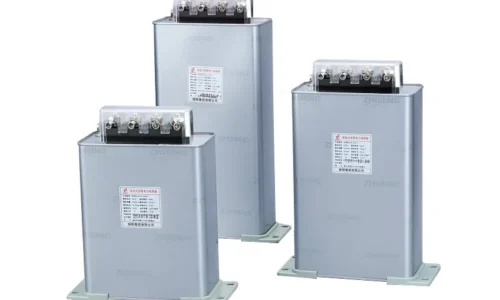
Internal Construction
Inside a 3-phase capacitor unit, there are typically either three separate capacitor elements — one per phase — or multiple smaller elements combined internally. The dielectric material varies, with polypropylene film being dominant in modern designs. Older installations might still contain capacitors with paper-oil or even PCB-based dielectrics, though the latter have been phased out due to environmental and health concerns.
Key internal components include:
- Capacitor elements with metallized film or foil-and-film construction
- Internal fuses on some designs, providing element protection
- Discharge resistors to safely bleed stored energy after disconnection
- Terminal connections rated for the unit’s voltage and current
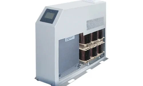
- Possibly internal series reactors for inrush limiting
Operating Characteristics of a 3-Phase Capacitor
Voltage and Frequency Sensitivity
The reactive power output of a capacitor, including a high voltage power capacitor, varies with both applied voltage and system frequency. Crucially, reactive power is proportional to the square of the voltage. This means a 10% voltage increase produces roughly 21% more kVAr output from the same unit. For high voltage power capacitor banks, this inherent voltage sensitivity is a critical design factor that can work for or against the stability of an installation.
On systems where voltage tends to run high, a high voltage power capacitor bank will deliver significantly more reactive power than its nameplate rating suggests. This over-delivery can sometimes push the system’s power factor beyond unity into a leading condition, which is often undesirable. In severe cases, it can create a feedback loop contributing to overvoltage conditions, potentially affecting other sensitive equipment connected to the same network.
Switching Transients
Energizing a 3-phase capacitor creates transient inrush current that can reach many times the steady-state current value. This happens because capacitors appear as nearly short circuits at the moment of connection — they charge rapidly from zero voltage, drawing substantial current in the process.
Managing inrush typically involves:
- Pre-insertion resistors that limit initial current then get bypassed
- Controlled switching devices that close at optimal voltage angle
- Series reactors permanently in circuit to limit inrush magnitude
- Switching capacitors individually rather than as a single large bank
Applications Where 3-Phase Capacitors Are Used
Common Industrial Applications
Power factor correction represents the majority of 3-phase capacitor applications. Factories, commercial buildings, water treatment plants, and similar facilities install capacitor banks to offset the reactive power demand of their motor loads.
Beyond power factor correction, 3-phase capacitors appear in:
- Harmonic filter circuits combined with reactors
- Voltage support on weak distribution systems
- Motor starting assistance in some configurations
- Resonant circuits for specialized industrial processes
Each application places different demands on the capacitor regarding switching frequency, harmonic exposure, and operating conditions. A capacitor suitable for continuous connection at a substation might fail quickly in an application requiring hundreds of daily switching operations.
FAQ
How long does a 3-phase capacitor typically last?
Life expectancy depends heavily on operating conditions. Under ideal circumstances — stable voltage, minimal harmonics, few switching operations, and moderate temperatures — a quality 3-phase capacitor might last 15 to 20 years or longer. Harsh conditions shorten this considerably. Elevated voltage, harmonic currents, frequent switching, and high ambient temperatures all accelerate dielectric degradation. Many manufacturers rate their capacitors for a specific number of switching operations or hours at rated conditions.
What happens if a 3-phase capacitor fails?
Failure modes vary. Some failures are quiet — internal open circuits that simply reduce compensation capacity without obvious symptoms until someone notices worsening power factor readings. Other failures are dramatic, involving internal short circuits, case rupture, or even fire in severe cases. Modern capacitors include protection features like internal fuses, pressure-sensitive disconnects, and case designs intended to fail safely if internal pressure builds. Still, failed capacitors should be treated with caution.
Can a 3-phase capacitor be oversized?
Absolutely — and it causes problems. An oversized 3-phase capacitor bank pushes power factor beyond unity into leading territory, which utilities dislike as much as lagging power factor. Overvoltage can develop, particularly on lightly loaded systems or during low-demand periods when voltage naturally runs high anyway. Overcompensation also wastes capital on unnecessary equipment and increases losses in the capacitors themselves since they now circulate current that serves no useful purpose.