Electricity bills can be surprisingly complicated. Beyond simple consumption charges, many commercial and industrial customers face penalties for something called poor power factor. It’s one of those technical concepts that facility managers often ignore—until the utility company sends an unexpectedly high bill.
This is where power factor correction capacitors enter the picture. These devices have been around for decades, quietly working in electrical systems worldwide. Yet many people outside the electrical engineering field have never heard of them.
Table of Contents
Understanding Power Factor Basics Before Exploring Power Factor Correction Capacitors
o grasp what these capacitors do, some background on power factor itself is necessary. Electrical systems deal with two types of power: real power (measured in kilowatts) and reactive power (measured in kilovars). Real power does actual work—running motors, lighting spaces, powering equipment. Reactive power, on the other hand, doesn’t perform useful work but is still required by certain electrical loads.
Power factor represents the ratio between real power and apparent power. A power factor of 1.0 (or unity) means all the power supplied is being used productively. Most industrial facilities, however, operate somewhere between 0.7 and 0.9. That gap represents inefficiency.
Inductive loads cause this problem. Motors, transformers, fluorescent lighting ballasts—these common industrial components draw reactive power that lags behind voltage. The result? More current flowing through the system than strictly necessary for the actual work being performed.
How A Power Factor Correction Capacitor Actually Works
A power factor correction capacitor introduces leading reactive power to counterbalance the lagging reactive power from inductive loads. It’s a bit like adding weight to one side of an unbalanced scale.
The principle is straightforward enough. Capacitors store electrical energy in an electric field and release it back into the circuit. When properly sized and installed, they offset the reactive power demands of inductive equipment. This doesn’t change how much real power the facility uses—it simply reduces the total current required to deliver that power.
Technical Specifications and Ratings
| Specification | Typical Range | Purpose |
|---|---|---|
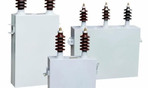
| Voltage Rating | 240V – 600V (LV) | Must match system voltage |
| kVAR Rating | 5 – 200+ kVAR | Reactive power compensation capacity |
| Frequency | 50Hz or 60Hz | Regional electrical standard |
| Temperature Class | -25°C to +55°C | Operating environment limits |
| Discharge Time | Under 1 minute | Safety requirement |
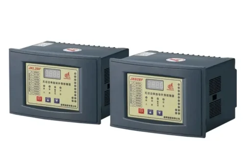
Selecting the right power factor correction capacitor requires careful calculation. Oversizing can actually push the power factor leading, which creates its own problems. Undersizing provides insufficient correction.
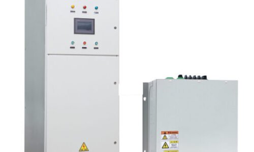
Installation Configurations
There are basically three ways to install these devices in an electrical system:
- Individual correction—capacitors installed directly at specific loads, typically large motors
- Group correction—capacitors serving several loads from a common point
- Central correction—a capacitor bank at the main distribution board serving the entire facility
Each approach has tradeoffs. Individual correction provides the most precise compensation but costs more to implement. Central correction is economical for installation but doesn’t reduce losses within the internal distribution network. Group correction falls somewhere in between, which is probably why it’s a popular choice for medium-sized operations.
Benefits of Installing Power Factor Correction Capacitors
The advantages extend beyond simply avoiding utility penalties, though that’s certainly a primary motivator for many facilities.
Reduced electrical losses throughout the distribution system represent real energy savings. Lower current means less heat generated in cables, transformers, and switchgear. Equipment runs cooler and often lasts longer as a result.
Additional benefits include:
- Increased system capacity without upgrading infrastructure
- Voltage stabilization, particularly at the end of long distribution runs
- Reduced carbon footprint due to decreased generation requirements
- Potential eligibility for utility incentive programs
Some facilities have recovered their investment in power factor correction equipment within a year or two, especially those previously paying substantial reactive power charges.
Common Applications and Industry Use Cases
Heavy manufacturing facilities with numerous motors represent the classic application. However, power factor correction capacitors appear across virtually every sector:
- HVAC systems in commercial buildings
- Pumping stations for water utilities
- Refrigeration plants and cold storage facilities
- Data centers (though these often have different power quality concerns)
- Mining operations with extensive conveyor systems
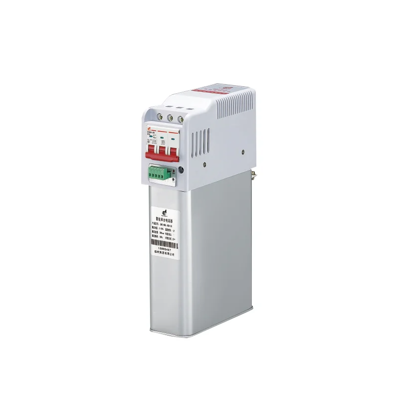
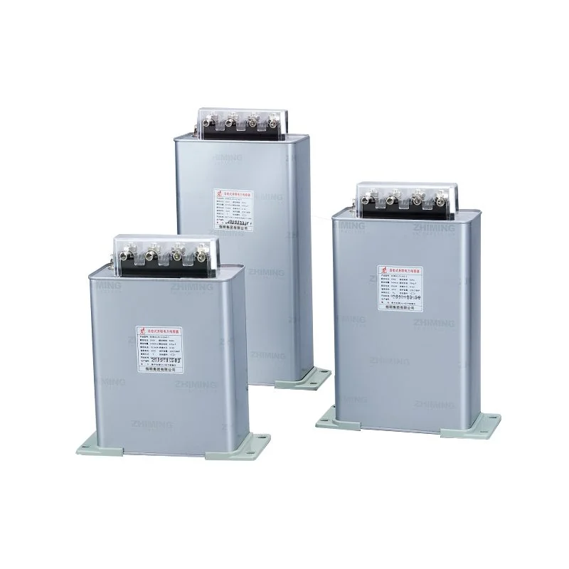
Most of these applications operate at distribution voltage levels, which is why the low voltage power capacitor has become such a common solution. These units typically handle systems up to 600V or so, making them suitable for the vast majority of commercial and industrial installations.
Maintenance and Safety Considerations
A power factor correction capacitor isn’t a install-and-forget device. Regular inspection helps identify potential issues before they become expensive problems.
Capacitors can fail, sometimes dramatically. Proper protection including fuses, overvoltage protection, and discharge resistors is essential. Harmonic distortion from variable frequency drives and other nonlinear loads can also stress capacitors beyond their design limits.
Final Thoughts
Power factor correction technology continues evolving alongside electrical systems themselves. While the basic principle remains unchanged—capacitive reactance offsetting inductive reactance—modern implementations have become more sophisticated. For facilities struggling with power factor penalties or simply seeking efficiency improvements, these capacitors offer a proven, cost-effective solution.
FAQ
How long does a power factor correction capacitor typically last?
Under normal operating conditions, quality capacitors last between 10 and 15 years. Factors like ambient temperature, harmonic exposure, and switching frequency affect lifespan. Some manufacturers offer warranties up to 10 years, which provides reasonable confidence in longevity.
Can power factor correction capacitors reduce electricity bills significantly?
Yes, though savings vary considerably depending on utility rate structures and existing power factor. Facilities with power factors below 0.85 and substantial reactive power charges might see bill reductions of 10-15% or more. The calculation is site-specific.
Are there situations where power factor correction capacitors shouldn't be used?
Certain conditions require caution. Systems with significant harmonic distortion may need detuned or filtered capacitor solutions rather than standard units. Also, leading power factor (over-correction) can cause voltage problems, so proper sizing remains critical.