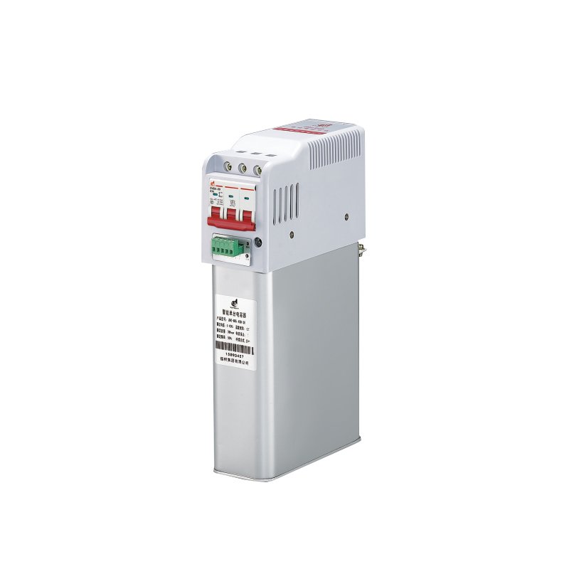
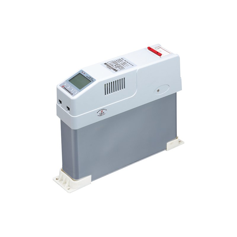
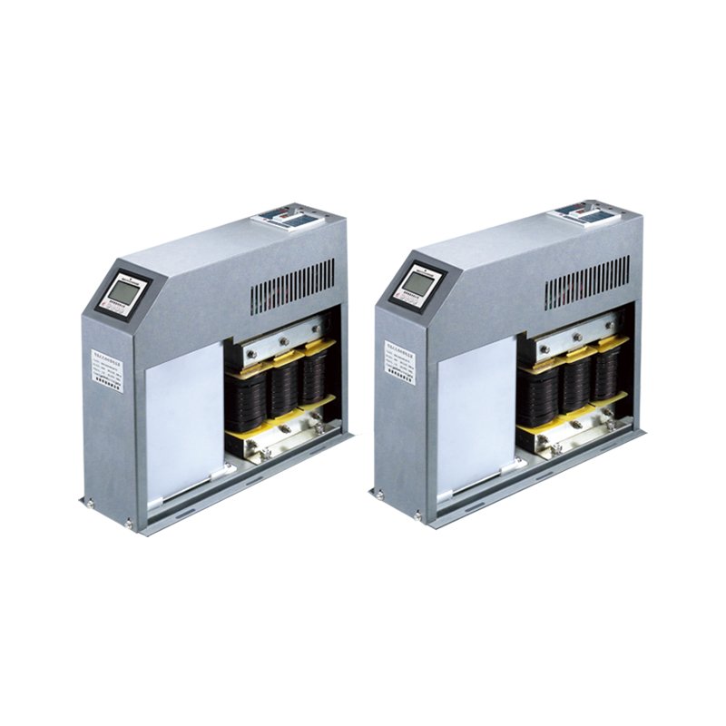
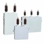
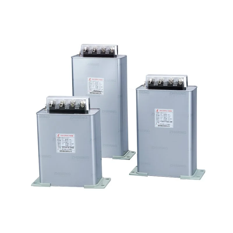
Zhiming Group focus on high and low voltage components and complete sets of equipment. Your needs are the starting point, and we design and tailor production accordingly to ensure that each piece of equipment is built to meet your power needs.
Maximize Efficiency & Power Factor
An intelligent power capacitor is an advanced reactive power compensation device that combines a low voltage power capacitor with built‑in control and protection electronics. Unlike a traditional fixed capacitor bank, this unit automatically measures the electrical network’s power factor, then switches capacitor stages on or off without external controller wiring. A typical intelligent power capacitor contains a micro‑processor based relay, a zero‑crossing switching mechanism (usually thyristors or special contactors), and internal protection against over‑temperature, over‑voltage, and harmonic overload. It is designed for direct connection to distribution panels up to 1 kV AC. You often see intelligent power capacitors installed in facilities with rapidly changing loads — such as welding equipment, elevators, or CNC machines — where manual capacitor switching would be ineffective.
| Function | Description | Typical Data / Range |
|---|---|---|
| Automatic Power Factor Correction | Measures real‑time power factor and switches capacitor stages to keep it within a target range | Target PF: 0.92 to 0.99 (adjustable) |
| Zero‑Crossing Switching | Closes or opens the contactor at voltage zero‑crossing to minimize inrush current and transient over‑voltage | Inrush current limited to ≤ 50 × In (typical) |
| Over‑Voltage Protection | Disconnects the capacitor when line voltage exceeds a safe threshold | Disconnect at 110% to 120% of rated voltage |
| Over‑Temperature Protection | Internal thermostat opens the circuit if core temperature rises too high | Trip at 55°C to 65°C (depending on model) |
| Harmonic Monitoring | Measures total harmonic distortion of current (THDi) and blocks switching when harmonic levels are excessive | Alarm or lock‑out at THDi > 20% |
| Manual Override Mode | Allows operator to force capacitor on or off via front panel buttons or remote communication | Optional Modbus RTU or dry contacts |
This table helps engineers and procurement teams quickly match the right intelligent power capacitor to their system requirements.
| Parameter | Typical Value / Range | Notes |
|---|---|---|
| Rated Voltage | 230 V to 690 V AC (50/60 Hz) | Select according to system line‑to‑line voltage |
| Rated Output (kvar) | 5 kvar, 10 kvar, 15 kvar, 20 kvar, 25 kvar, 30 kvar | Per single unit |
| Number of Stages | 1 or 2 stages per enclosure | Multi‑stage units for finer correction |
| Power Factor Measurement Accuracy | ±0.5% or better | Built‑in metering |
| Switching Technology | Thyristor (semiconductor) or reinforced contactor | Thyristor type for fast‑changing loads |
| Response Time | ≤ 20 ms (thyristor) / ≤ 2 seconds (contactor) | From measurement to switch action |
| Discharge Resistor | Built‑in, discharge to ≤ 50 V within 1 minute | Safety requirement per IEC 60831 |
| Protection Level | IP20 (standard) / IP54 (optional for dusty or wet areas) | Enclosure rating |
| Ambient Operating Temperature | –25°C to +55°C | Derating required above 50°C |
| Communication Interface | Optional: RS485 Modbus RTU / 4‑20 mA analog output | Remote monitoring and control |
| Standards Compliance | IEC 60831‑1, IEC 60831‑2, UL 810 (selected models) | Check local certification |
Where Our Intelligent Power Capacitor Delivers Proven Results
An intelligent power capacitor is not simply a standard capacitor with a controller bolted on. Below are field situations where our intelligent power capacitor automatically maintains target power factor under fluctuating loads, reduces utility charges for reactive energy without manual tuning, and prevents capacitor failure caused by harmonic resonance or over‑voltage spikes.
Our intelligent power capacitor comes as a complete assembly: contactor, discharge resistor, control logic, and protection sensors are all inside one metal enclosure. You do not need to buy a separate power factor regulator or wire external current transformers to a distant controller.
any capacitor failures come from switching inrush currents that weld contactors or swell dielectrics. ZHIMING intelligent power capacitors use thyristor‑based zero‑crossing switching in standard models. The semiconductor turns on exactly when the voltage waveform crosses zero, so inrush current stays low.
Running a power capacitor in an environment with high harmonic distortion can cause overload or even explosion. Our intelligent power capacitor continuously monitors total harmonic distortion of the line current.
When the grid voltage rises above 110% of nominal, many conventional capacitors simply run overstressed until their internal protection finally fails. ZHIMING’s intelligent power capacitor includes a solid‑state voltage monitoring circuit that opens the switching device within one cycle when over‑voltage is detected.
The same ZHIMING intelligent power capacitor works on 50 Hz or 60 Hz systems without reprogramming. This is helpful for original equipment manufacturers who ship panels to different countries, or for facility managers who have mixed frequency sources.
For installations with multiple intelligent power capacitors spread across a large plant floor, walking to each unit to read status is inefficient. Our units support optional RS485 Modbus RTU communication.
A leading power capacitor manufacturer with over 25 years of experience is here to answer all your inquiries—covering any product-related issues, business questions, or service-related concerns.
Still Have Questions? We’re Here to Help
Didn’t find what you were looking for?
Contact Us Anytime
Yes. The intelligent power capacitor measures the line current through an external low voltage current transformer to calculate power factor. You can use any standard CT with 5 A or 1 A secondary output.
There is no fixed limit, but you must set one unit as the master and others as slaves if you want coordinated switching. Each unit can also work independently, switching its own stage based on the same current signal. For more than six units, we recommend using a central power factor controller instead of multiple stand‑alone intelligent types.
It can work, but you must adjust the over‑voltage and under‑voltage thresholds to match the generator’s typical regulation band (for example 5% to 8% variation). Also avoid switching the capacitor when the generator is starting or stopping, as frequency may drift outside 50/60 Hz range.
Yes, but you must order a model rated for the correct voltage and connection type (single‑phase or three‑phase). Three‑phase models are delta or wye connected; single‑phase models are typically used across phase‑to‑neutral. Check the datasheet because internal switching logic differs.
If your load varies more than 30% across a working day (for example welding robots, large air compressors cycling on and off, or heavy batch mixers), an intelligent power capacitor will save more reactive energy than a fixed bank. Fixed banks cause over‑correction during light load periods, leading to leading power factor and utility penalties. The intelligent type eliminates that risk.
Contact us, we power your needs.
30+ years of focused commitment,
Powering progress, empowering lives.