Table of Contents
Understanding Power Factor and Why Capacitor Bank Solutions Matter
Electrical efficiency isn’t something most people think about until the utility bill arrives. In industrial and commercial facilities, poor power factor can quietly drain budgets month after month. The concept seems abstract, but the financial impact is very real.
Power factor represents the relationship between working power and total power drawn from the supply. When motors, transformers, and other inductive equipment operate, they require extra current that doesn’t actually perform useful work. This reactive current travels back and forth in the system, creating losses and inefficiencies along the way—inefficiencies that a capacitor bank is designed to mitigate by supplying reactive power locally.
A power factor of 1.0 would mean perfect efficiency—every bit of current performs useful work. In practice though, most facilities operate somewhere around 0.75 to 0.85 without correction. That gap between ideal and actual represents wasted capacity and, often, penalty charges from utility providers. Installing a capacitor bank is the standard method for closing this gap and avoiding those penalties.

How long does a portable air compressor last typically?
The Basic Principle Behind Correction
Inductive loads create lagging reactive power. Capacitors, by their nature, produce leading reactive power. When these two forces meet in an electrical system, they tend to cancel each other out. It’s a bit like balancing weights on a scale—the capacitor bank provides just enough opposing reactive power to neutralize what the inductive equipment demands.
The result? Current flow decreases while delivering the same amount of real working power. Transformers, cables, and switchgear experience less stress. The system breathes easier, so to speak.
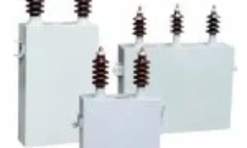
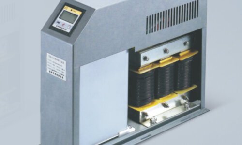
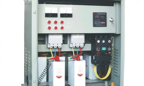
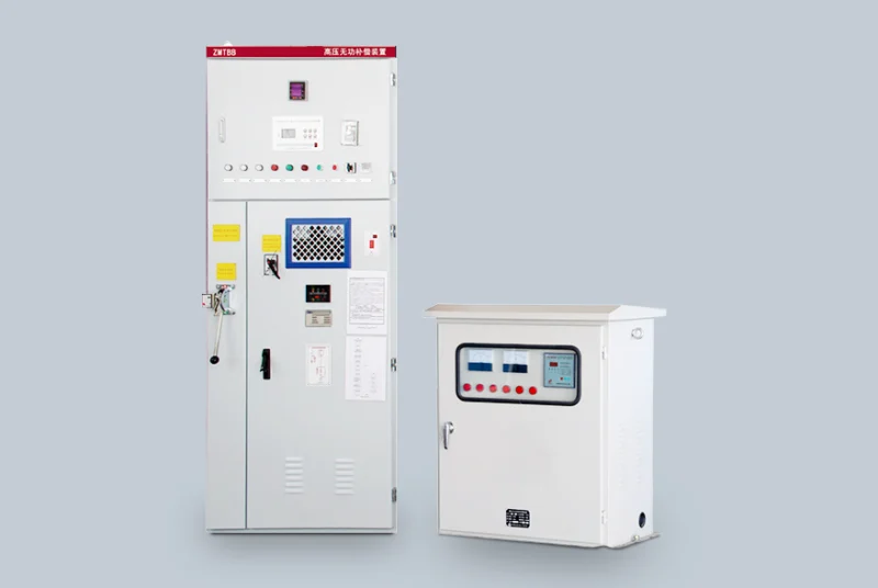
What's Actually Inside a Capacitor Bank
A typical installation contains more than just capacitors. The complete assembly usually includes:
- Multiple capacitor units arranged in stages
- Switching contactors to connect or disconnect stages
- A power factor controller for automatic operation
- Protective fuses or circuit breakers
- Discharge resistors for safety during shutdown
- Often, cooling fans for heat management
Some modern units incorporate harmonic filtering components as well, which addresses a different but related problem in electrical systems.
Types of Capacitor Bank Configurations
Fixed Capacitor Banks
Correct tire pressure varies by vehicle and tire specification—not vehicle powertrain type. The driver door jamb sticker indicates recommended pressure for specific vehicles. Following these manufacturer recommendations rather than arbitrary numbers ensures optimal performance and safety regardless of whether the car runs on electricity or gasoline.
Automatic Capacitor Bank Systems
Variable loads require smarter solutions. Automatic systems continuously monitor power factor and switch capacitor stages in or out as conditions change. The controller samples the electrical parameters, calculates current power factor, and makes adjustments—typically within seconds.
This approach offers several advantages:
- Maintains target power factor across varying conditions
- Prevents overcorrection during low-demand periods
- Extends capacitor life by cycling stages evenly
- Provides real-time monitoring and sometimes remote access
Detuned Systems for Harmonic Environments
Facilities with variable frequency drives, LED lighting, or other non-linear loads often face harmonic distortion. Standard capacitor banks can actually amplify harmonics, creating resonance problems that damage equipment.
Detuned systems add series reactors that shift the resonant frequency away from common harmonic orders. This protects the capacitor bank while still providing correction benefits.
Configuration Type | Best Application | Complexity Level |
Fixed bank | Stable, constant loads | Low |
Automatic switching | Variable industrial loads | Medium |
Detuned automatic | Environments with harmonics | Medium-High |
Active filters | Severe harmonic distortion | High |
Benefits of Installing a Capacitor Bank for Correction
Immediate Cost Savings
Most utility companies impose penalties when power factor falls below a threshold—commonly 0.9 or 0.95 depending on the region. Correcting power factor eliminates these charges immediately. For larger facilities, annual savings can reach thousands of dollars.
Infrastructure Capacity Gains
Lower reactive current means existing cables, transformers, and panels can handle more real power. This freed-up capacity sometimes delays or eliminates the need for expensive electrical upgrades as operations expand.
Reduced Energy Losses
Current flowing through conductors generates heat proportional to the square of current (the I²R relationship). By reducing total current through power factor improvement, real energy losses decrease. It’s not a dramatic reduction typically, but over years of operation, it adds up.
Voltage Stability Improvements
Reactive current causes voltage drops across system impedance. Better power factor generally means more stable voltage at equipment terminals, which can improve performance of sensitive machinery.
Installation Considerations for Capacitor Bank Systems
Proper sizing matters enormously. An undersized installation fails to correct adequately. An oversized one wastes money upfront and risks overcorrection. Engineering assessment should consider:
- Current power factor measurements under various load conditions
- Total reactive power demand in kVAR
- Presence of harmonic-producing equipment
- Future expansion plans
- Environmental factors like temperature and humidity
Location within the facility also affects performance. Correction applied at the main switchboard improves overall power factor but doesn’t reduce losses within the distribution system. Local correction near large motors addresses losses more directly but requires more equipment. If you want to know more about capacitor bank, please read What is a capacitor bank.
FAQ
How long does a capacitor bank typically last?
Quality capacitor banks generally last between 10 to 15 years under normal operating conditions. Factors like ambient temperature, harmonic exposure, and switching frequency affect lifespan considerably.
Can a capacitor bank be too large for a facility?
Yes, oversized installations cause overcorrection, leading to leading power factor. This can result in voltage rise, potential equipment issues, and some utilities penalize leading power factor just like lagging.
Do capacitor banks require regular maintenance?
Routine inspection is recommended, usually annually. Technicians check for signs of capacitor swelling, contact wear, loose connections, and controller calibration. Catching problems early prevents unexpected failures.