Poor power factor plagues nearly every industrial and commercial electrical system, driving up energy costs, straining transformers, and triggering utility penalties. A properly connected capacitor bank offsets lagging reactive power from inductive loads, bringing power factor closer to unity and unlocking consistent efficiency gains. This guide breaks down the full workflow of integrating a capacitor bank, from preliminary sizing to final wiring checks, with field-tested insights for reliable, long-term performance.
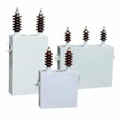
Table of Contents
Why Capacitor Bank Installation Matters for Power Factor Optimization
Inductive loads—motors, transformers, compressors, and lighting ballasts—dominate most commercial and industrial setups, creating a phase shift between voltage and current that lowers power factor. This mismatch forces the grid to supply excess reactive power, wasting capacity and increasing line losses. A capacitor bank delivers leading reactive power locally, neutralizing lagging currents and reducing the burden on the main supply. Even modest power factor improvements (from 0.75 to 0.95) cut energy waste significantly, extend equipment lifespan, and eliminate demand charges tied to low power factor.
Key benefits of a well-connected capacitor bank include:
- Reduced reactive power draw from the utility grid, lowering monthly electricity expenses
- Stabilized voltage levels across the distribution network, minimizing voltage dips under heavy load
- Lower thermal stress on cables, switchgear, and transformers, reducing maintenance frequency
- Compliance with utility power factor standards, avoiding penalty fees and surcharges
Pre-Connection Steps: Sizing and Selecting the Right Capacitor Bank
Calculating Required Capacitor Bank Rating (kVAR)
Before wiring, accurate sizing ensures the capacitor bank matches the system’s reactive power deficit without overcorrection. Overcompensation can lead to voltage spikes and equipment damage, while undersizing fails to deliver meaningful power factor gains. Sizing relies on real power (kW), initial power factor, and target power factor, with standard multipliers simplifying field calculations.
Choosing Capacitor Bank Configuration
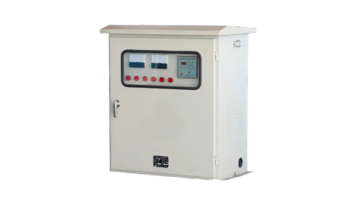
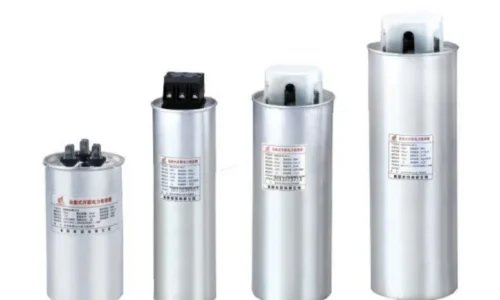
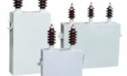
Capacitor banks for power factor correction come in two core configurations, each suited to specific load profiles and system voltages. Fixed banks are ideal for steady, constant loads, offering simplicity and low cost. Automatic banks use power factor controllers to switch capacitor modules on/off, adapting to fluctuating loads common in manufacturing and commercial buildings. Most low-voltage systems use delta-connected capacitor banks for higher reactive power output, while star (wye) connections are preferred for medium-voltage setups to reduce insulation stress.
Step-by-Step Capacitor Bank Connection Process
Safety is non-negotiable during low voltage power capacitor bank installation—always de-energize the system, verify voltage absence with a multimeter, and discharge residual capacitor voltage before handling wiring. Follow these ordered steps for a secure, compliant connection:
Mount the capacitor bank in a well-ventilated, dry enclosure near the main distribution panel or load center, minimizing cable length to reduce losses.
Install protective devices: circuit breakers, fuses, and surge arresters to shield the capacitor bank from overcurrent, short circuits, and voltage transients.
Run appropriately sized copper cables from the main busbar to the capacitor bank terminals, matching phase sequence (R-Y-B) for three-phase systems.
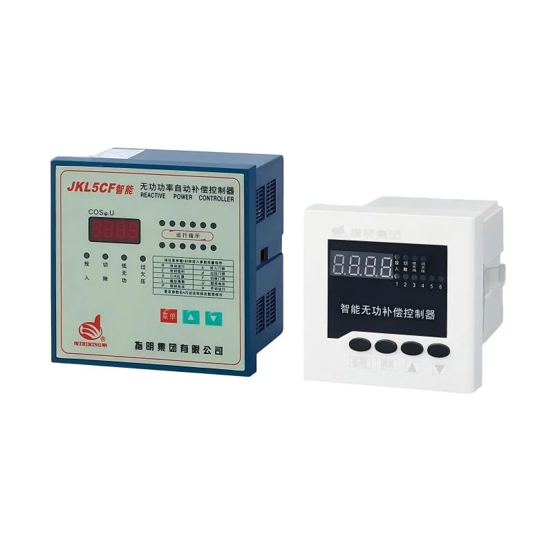
Wire the power factor controller (for automatic banks) to current transformers (CTs) installed on the main incoming feeder, ensuring accurate power factor monitoring.
Connect the capacitor bank in parallel with the inductive load network—parallel wiring is critical, as series connections disrupt voltage and fail to correct power factor effectively.
Secure all terminals, tighten connections to torque specifications, and insulate exposed conductors to prevent arcing or short circuits.
Gradually energize the system, monitor voltage and current readings, and adjust the capacitor bank staging (for automatic units) to hit the target power factor.
Mount the capacitor bank in a well-ventilated, dry enclosure near the main distribution panel or load center, minimizing cable length to reduce losses.
Install protective devices: circuit breakers, fuses, and surge arresters to shield the capacitor bank from overcurrent, short circuits, and voltage transients.
Run appropriately sized copper cables from the main busbar to the capacitor bank terminals, matching phase sequence (R-Y-B) for three-phase systems.
Wire the power factor controller (for automatic banks) to current transformers (CTs) installed on the main incoming feeder, ensuring accurate power factor monitoring.
Connect the capacitor bank in parallel with the inductive load network—parallel wiring is critical, as series connections disrupt voltage and fail to correct power factor effectively.
Secure all terminals, tighten connections to torque specifications, and insulate exposed conductors to prevent arcing or short circuits.
Gradually energize the system, monitor voltage and current readings, and adjust the capacitor bank staging (for automatic units) to hit the target power factor.
Critical Wiring Checks Post-Installation
After connecting the capacitor bank, perform baseline tests to confirm functionality and safety. Measure power factor with a power quality analyzer to verify improvement, check for abnormal heating or humming in the capacitor bank, and inspect for loose connections. Document initial readings for ongoing maintenance tracking, as gradual degradation in power factor signals capacitor wear or wiring issues.
FAQ
Why is parallel connection mandatory for capacitor bank power factor correction?
Parallel connection lets the capacitor bank supply reactive power directly to inductive loads without altering the main circuit voltage. Series wiring would create voltage drops and reduce current flow, defeating the purpose of power factor improvement. Parallel setup also allows individual capacitor modules to be serviced without shutting down the entire compensation system.
Can a capacitor bank be connected to a single-phase load for power factor improvement?
Yes, single-phase capacitor banks are designed for residential and small commercial single-phase systems. The wiring process mirrors three-phase setups but uses single-phase protection devices and connects across line and neutral terminals. Sizing is adjusted to match the single-phase load’s reactive power demand, ensuring balanced correction without overvoltage.
How to avoid overcorrection when connecting a capacitor bank?
Overcorrection (power factor above 1.0) causes voltage instability and equipment damage, often from oversized capacitor banks or improper controller tuning. Use an automatic capacitor bank with a smart power factor controller to stage capacitors based on real-time load conditions, perform accurate pre-installation sizing, and avoid over-specifying kVAR rating. Regular power factor monitoring helps catch overcorrection early for quick adjustments.