Standing in a electrical room full of switchgear can be intimidating. There are breakers, meters, and conduits running everywhere. Among all this hardware, the addition of a few gray boxes—power capacitors—can seem deceptively simple. But how they are wired in makes all the difference. It’s not just about slapping a capacitor on the wall and hoping for the best. The connection method determines whether the system actually achieves that sought-after power factor improvement or just sits there looking expensive.
The choice of connection usually comes down to the nature of the loads. Is the facility running one big motor all day, or are there dozens of small machines cycling on and off? The answer dictates whether the connection is direct, in a group, or part of an automatic bank. Getting it right means lower bills; getting it wrong can mean nuisance tripping or even equipment damage.
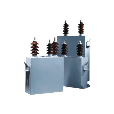
Table of Contents
Individual Connection
This is about as straightforward as it gets. A capacitor is connected directly to the terminals of a specific piece of equipment, usually a large induction motor. The wiring typically runs from the motor starter’s load side right to the capacitor unit. The idea is to switch the capacitor on and off simultaneously with the motor.
Why do it? It provides correction exactly where the reactive power is needed.
Where is it used? Large motors that run for long periods, like pumps, fans, or compressors.
There is a practical rule of thumb here. The capacitor should be connected on the load side of the motor starter, but ahead of the motor overload relays. This is important because the capacitor reduces the current flowing through the lines, and if it were placed after the overloads, it could trick the heater elements into thinking the motor is running cooler than it actually is. That’s a safety hazard.
Sizing for Individual Motors
The math isn’t too painful. The goal is to reduce the reactive current drawn from the supply, not to over-correct the motor. Typically, the capacitor kVAR (kilovar) rating is chosen to be about 90-95% of the motor’s magnetizing current. This brings the power factor improvement to around 95% lagging, which is the sweet spot. Going to 100% (unity) risks self-excitation when the motor is switched off, which can cause voltage spikes. It’s a fine line, but an important one.
Group Connection
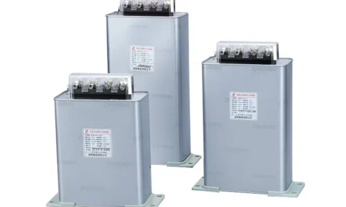
Sometimes, connecting a capacitor to every single motor is impractical. There might be dozens of small motors, or the loads might be spread out over a large facility. In that case, a group connection makes more sense. A single low voltage power capacitor bank—or a bank of several steps—is connected to a main distribution bus, feeding a whole section of the factory.
This method is less about perfect, localized correction and more about improving the overall system. The bank of low voltage power capacitors supplies the reactive power for everything downstream. It’s cheaper to install than multiple individual units, and it requires less maintenance overall. However, it doesn’t reduce losses in the branch feeders running to the individual motors, because the reactive current still travels through those smaller wires.
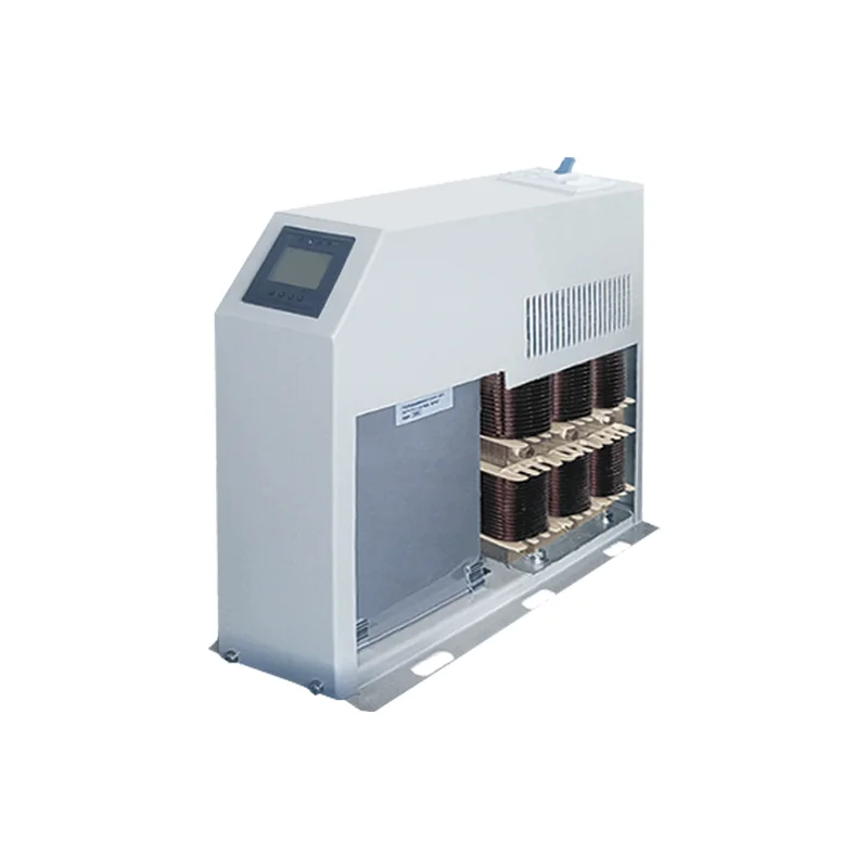
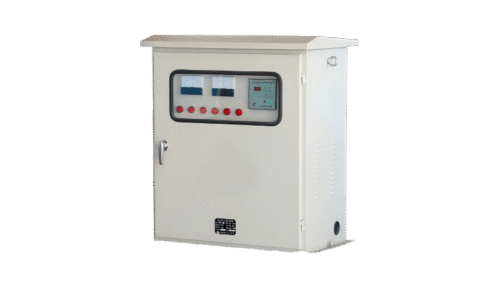
Automatic Connection
Now, here’s where it gets a bit more sophisticated. If a facility has loads that come and go throughout the day—say, a welding shop or a manufacturing line with multiple shifts—a fixed group bank won’t cut it. If the load drops, a fixed bank will over-correct, sending the power factor into a leading (capacitive) territory, which can be just as problematic as a lagging one.
An automatic connection solves this. It uses a power factor controller (a small microprocessor) that constantly monitors the system. When the power factor drops below a set threshold, the controller switches on smaller capacitor steps one by one.
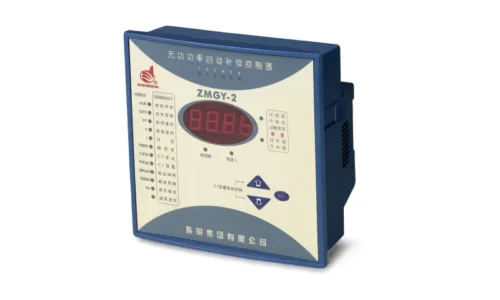
How the Automatic Bank is Wired
The wiring here is more involved than a simple individual connection. It requires:
A Current Transformer (CT): This senses the current on the main incoming lines and sends a signal to the controller.
The Controller: The brain of the operation. It reads the CT signal and decides if more capacitance is needed.
Contactor Steps: For each capacitor stage, there is a contactor that the controller energizes to connect that stage to the bus.
Detuning Reactors (Often): In modern systems, reactors are wired in series with the capacitors to protect against harmonic currents from VFDs.
It’s a neat setup. When a big machine kicks on, the power factor dips, and the controller responds within seconds, clicking in another stage of capacitors to bring it back up. It’s a dynamic process, constantly adjusting.
Safety and Installation Considerations
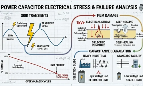
Regardless of the connection type chosen, some universal rules apply. Capacitors store energy. Even when the power is off, a capacitor bank can hold a lethal charge. Therefore, discharge devices (usually resistors) must be connected across the terminals to bleed the voltage down to safe levels within a few minutes.
Also, fusing is critical. Capacitors can fail, and when they do, they need to be isolated quickly to prevent a cascading failure or a fire. High-rupture-capacity (HRC) fuses are standard practice. And finally, the connecting cables must be rated for the capacitive current, which can be higher than the simple resistive current due to the leading nature of the load.
FAQ
Can a power capacitor be connected to any motor?
Generally yes, but the motor must be compatible. Motors that are switched on and off frequently (like crane motors or jogging applications) are not ideal for fixed capacitors because the discharge time might not be sufficient, causing high inrush currents. Also, motors controlled by VFDs usually should not have standard capacitors connected to their output; they require harmonic filters instead.
Why does the power capacitor need to be on the load side of the overload relay?
It’s for protection. The capacitor reduces the line current. If the capacitor is placed after the overload relay, the relay will see a lower current than the motor is actually drawing. In an overload condition, the motor could overheat while the relay, fooled by the lower current, fails to trip. Placing it before the relay ensures the relay sees the true motor current.
What happens if a power capacitor bank is left connected when the load is turned off?
If it’s a fixed bank on a dedicated feeder, and the feeder is still energized, the bank will continue to supply leading current back into the system. This can cause a voltage rise on the bus, which is potentially damaging to other equipment that is still online. This is why automatic controllers are essential for variable loads, and why individual banks are usually switched with the motor itself.