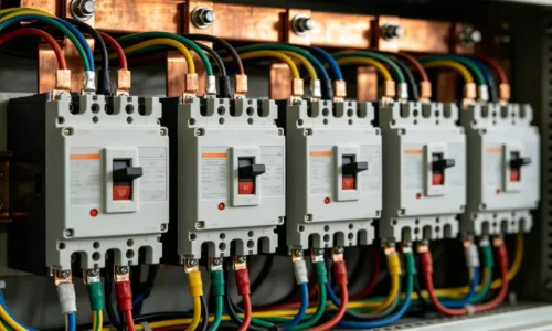
When looking at electrical diagrams, one often sees a simple symbol composed of two parallel lines: 卝. This is the representation of C, or capacitance. However, in the heavy-duty world of industrial electricity, this symbol translates into a physical device that is anything but simple. The power capacitor is a cornerstone of modern energy efficiency, sitting quietly in cabinets, humming along while saving industries significant amounts of money. It is fascinating to observe how such a static device creates such dynamic changes in a power system.
Table of Contents
The Core Concept Behind a Power Capacitor
At a fundamental level, the function of a power capacitor is tied directly to its physical makeup. It isn’t magic; it is physics. The essence of capacitance is often described by a formula that balances three things: the dielectric constant of the material inside, the area of the electrode plates, and the distance between them.
Ideally, to get more power, one would want huge plates and a tiny distance between them. It is a bit of a game between space and safety. In the manufacturing process, there is a constant push and pull. For instance, metallized polypropylene films are standard in the industry now. Manufacturers wind these films tightly to increase the effective area, creating a massive surface area inside a relatively small can. They also try to keep the film thickness down to the micron range—sometimes just 5 or 6 micrometers.
But here is the catch. If the film is made too thin in pursuit of higher performance, the lifetime of the power capacitor drops significantly. It is a delicate balance. A device that is too fragile won’t last in the harsh reality of an electrical grid, no matter how good its theoretical specs are.
Materials Selection for the Power Capacitor
One might wonder why every capacitor isn’t made of the material with the highest numbers. Ceramics, for example, have massive dielectric constants. Yet, the industry overwhelmingly prefers polypropylene for AC power applications.
The reason lies in stability and loss. Although the dielectric constant of polypropylene films is only around 2.2—which looks tiny compared to the thousands you see with Barium titanate ceramics—they are incredibly robust. They handle high voltage without falling apart and don’t waste much energy as heat. In an AC environment, low loss is everything.
Below is a breakdown of how different materials stack up in real-world usage:
| Material Type | Dielectric Constant (εr) | Primary Advantage | Typical Usage Scenario |
|---|---|---|---|
| Polypropylene Film | 2.2 – 2.5 | High frequency, low loss, high withstand voltage | Power capacitor cabinet, filtering |
| Aluminum Electrolyte | 8 – 10 | High capacity, effective for low voltage | DC power energy storage |
| Barium Titanate Ceramic | 1,000 – 15,000 | Extreme dielectric constant, allows miniaturization | High-voltage pulsed, low-profile electronics |
| Metallized Films | 2.2 – 2.5 | Self-healing properties | AC system compensation |
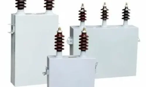
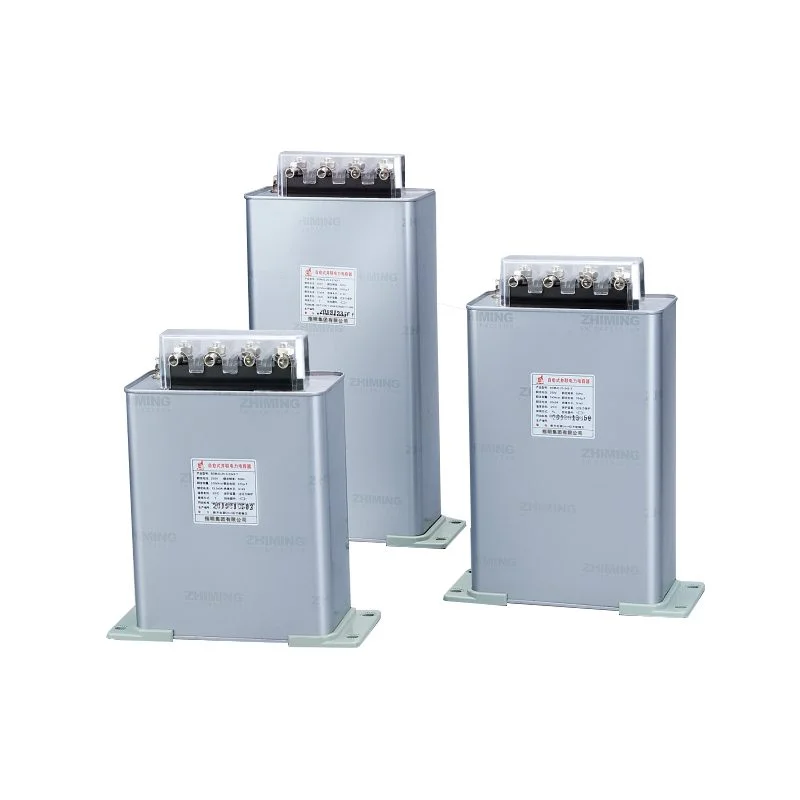
Inside the Structure of a Modern Power Capacitor
Visualizing the inside of these metal cans can be difficult with dry text alone, but the engineering is quite clever. The construction isn’t just a roll of tape; it is a sophisticated system designed to fail safely if it has to fail at all.
Electrodes and the Self-Healing Mechanism
The electrodes are usually made of metallized polypropylene film or aluminum foil. The metallized film is incredibly thin, around 0.02 to 0.03 microns. This thinness allows for a feature that seems almost biological: self-healing.
When a local breakdown occurs inside the power capacitor—maybe due to a voltage spike—the energy vaporizes the metal layer right around the breakdown point. The “wound” effectively cauterizes itself, isolating the fault. The capacitor keeps working. This prevents the kind of catastrophic short-circuit failures that used to be more common with older technologies.
Enclosure and Thermal Management
Heat management is critical. To address this challenge, the gaps between the plates are typically filled with vacuum-impregnated mineral oil or resin. This serves not only for insulation but also helps transfer heat away from the core. The mineral oil can also raise the partial discharge inception voltage, technically preventing internal sparking. This design is also employed in low-voltage power capacitors to ensure their stable operation.
For the outer enclosure, the common options are:
Metal enclosures (galvanized steel): Used for high-capacity units. Their corrugated walls act as heat sinks, keeping the temperature rise within specified limits (typically not exceeding 20K). Some high-capacity low-voltage power capacitors also utilize this robust and thermally efficient structure.
Plastic housings: Flame-retardant, used for smaller modular units. Commonly found in compact low-voltage power capacitor modules.
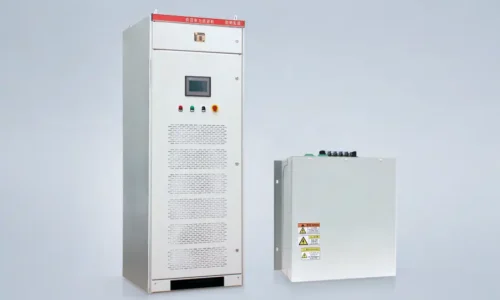
The Economic Role of the Power Capacitor
Power Factor and Energy Savings
Inductive loads like motors are messy. They generate hysteresis reactive power, which clogs up the system. By installing a power capacitor, a facility performs reactive compensation. This smooths out the flow.
The economic impact is real. Taking a standard 10kV distribution system as an example, investing in just 1kvar of capacitance can reduce power loss by about 150 to 200 kWh per year. For a typical factory, this can shave 3% to 8% off the total electricity bill. It pays for itself.
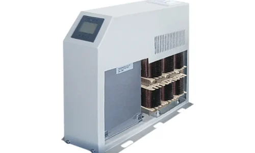
Voltage Stabilization
Beyond money, there is stability. Voltage fluctuations can damage sensitive equipment. A properly sized capacitor bank can shrink voltage fluctuation ranges from ±10% down to a tight ±3%. However, one must be careful with harmonics. In environments with lots of “noise” (5th and 7th harmonics), simply adding a capacitor can cause resonance issues. That is why you often see a reactor connected in series—usually with a 7% reactance rate—to dampen the resonance.
FAQ
What is the most critical parameter when selecting a power capacitor?
While many look at capacitance first, the withstand voltage and temperature stability are arguably more important for longevity. You must also consider the loss angle (tanδ). Relying solely on the dielectric constant is a mistake; you need a balance of parameters that fits your specific grid conditions.
Can a power capacitor explode?
Technically, yes, if safety measures fail. However, modern designs are very safe. They include over-pressure disconnectors and temperature sensors. If the internal pressure builds up due to gas from overheating oil or film breakdown, the top of the can expands and mechanically breaks the connection, disconnecting the device before it can rupture dangerously.
Why is the self-healing property important?
It extends the service life of the unit dramatically. Without self-healing, a single microscopic defect in the dielectric film would cause a total short circuit, rendering the device useless immediately. With self-healing, the power capacitor tolerates small internal faults and continues to operate, which is vital for maintaining uptime in industrial plants.