Getting power factor correction right matters more than many facility managers realize. Oversized capacitors cause problems. Undersized ones waste money on utility penalties that could have been avoided. The calculation itself isn’t terribly complicated, but understanding what goes into it—and why—makes the difference between effective correction and expensive guesswork.
A power capacitor doesn’t just get installed randomly. Proper sizing requires knowing current conditions, target improvements, and the actual reactive power compensation needed. Skip the math, and the results disappoint.
Table of Contents
Why Power Factor Correction Matters for Electrical Systems
Before diving into calculations, some context helps. Electrical systems draw two types of power from the grid: real power (measured in kilowatts) that performs actual work, and reactive power (measured in kilovolt-amperes reactive, or kVAR) that supports magnetic fields in motors and transformers but doesn’t accomplish productive tasks.
The ratio between real power and total apparent power defines power factor. When that ratio drops below acceptable levels—typically anything under 0.90 for most utilities—penalties accumulate. Equipment runs less efficiently. Infrastructure gets stressed unnecessarily.
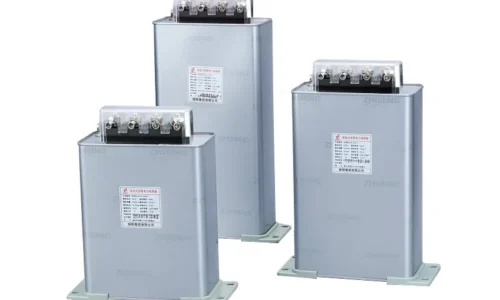
Installing the right power capacitor addresses these issues by supplying reactive power locally. The grid no longer needs to provide it. Power factor improves. Bills drop.
But how much capacitance does a specific situation actually require?
The Basic Formula for Power Capacitor Sizing
The fundamental calculation relies on knowing three things: existing real power load, current power factor, and desired power factor after correction.
The formula looks like this:
Required kVAR = kW × (tan φ₁ – tan φ₂)
Where:
- kW represents the real power load
- φ₁ is the angle corresponding to current power factor
- φ₂ is the angle corresponding to target power factor
- tan φ represents the tangent of these angles
Converting power factor to angles requires some trigonometry. For a power factor of 0.75, the corresponding angle equals arccos(0.75), which works out to about 41.4 degrees. The tangent of that angle is roughly 0.882.
This sounds more complicated than it plays out in practice. Tables exist for exactly this purpose.
Using Multiplier Tables for Quick Calculations
Rather than calculating tangent values manually, most engineers reference multiplier tables. These provide correction factors based on existing and target power factors.
| Existing PF | Target 0.90 | Target 0.95 | Target 1.00 |
|---|---|---|---|
| 0.70 | 0.536 | 0.691 | 1.020 |
| 0.75 | 0.398 | 0.553 | 0.882 |
| 0.80 | 0.266 | 0.421 | 0.750 |
| 0.85 | 0.135 | 0.291 | 0.620 |
| 0.90 | — | 0.156 | 0.484 |
To find required kVAR, simply multiply the load in kW by the appropriate table value. A 200 kW load at 0.75 power factor targeting 0.95 would need: 200 × 0.553 = 110.6 kVAR.
The power capacitor bank would need to supply approximately 110 kVAR of reactive compensation.
Step-by-Step Calculation Process
Working through an actual example clarifies the process. Consider a manufacturing facility with the following characteristics:
- Total real power demand: 350 kW
- Measured power factor: 0.72
- Utility penalty threshold: 0.90
- Target power factor: 0.95 (allowing some margin)
The calculation proceeds as follows:
- Identify current power factor angle: arccos(0.72) = 43.95°
- Calculate tangent of current angle: tan(43.95°) = 0.964
- Identify target power factor angle: arccos(0.95) = 18.19°
- Calculate tangent of target angle: tan(18.19°) = 0.329
- Determine kVAR requirement: 350 × (0.964 – 0.329) = 222.25 kVAR
The facility needs roughly 225 kVAR of power capacitor compensation. Standard capacitor banks come in specific sizes, so rounding to available options makes sense.
Accounting for Load Variations
Fixed calculations assume constant loads. Reality rarely cooperates. Most facilities experience significant load variations throughout operating hours—shift changes, seasonal differences, equipment cycling on and off.
Options for handling this include:
- Sizing for average load conditions and accepting some under or over-correction
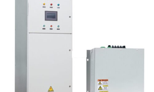
- Installing automatic capacitor banks that switch stages based on measured power factor
- Using a combination of fixed base compensation plus automatic trim adjustment
Automatic systems cost more upfront but deliver better results in variable load environments. The power capacitor stages engage and disengage as conditions change, maintaining correction without operator intervention.
Practical Considerations Beyond Basic Math
The calculation provides a starting point. Several real-world factors influence final decisions.
Harmonic Distortion Concerns
Modern facilities often contain equipment generating harmonic currents—variable frequency drives, LED lighting systems, switching power supplies. Standard power capacitor installations can interact badly with harmonics, potentially amplifying distortion and causing equipment damage.
Warning signs include:
- Audible humming from capacitors or transformers
- Premature capacitor failures
- Unexplained equipment malfunctions
- Overheating of electrical components
Detuned reactor systems address harmonic issues by adding inductance that shifts resonant frequencies away from common harmonic orders. The additional cost provides protection worth having in harmonic-rich environments.
Voltage Rise Effects
Adding reactive compensation raises system voltage slightly. Usually this proves beneficial—voltage drops from the utility get partially offset. But excessive correction can push voltage above acceptable limits.
A general guideline suggests voltage rise stays under 2-3% from capacitor installation. Larger corrections may require coordination with the utility or installation of voltage regulation equipment.
Equipment Selection After Calculation
Once kVAR requirements are established, selecting appropriate equipment involves additional choices:
- Fixed versus automatic bank configuration
- Number of switching stages for automatic systems
- Contactor versus thyristor switching technology
- Indoor versus outdoor enclosure ratings
- Detuned reactor requirements based on harmonic analysis
A qualified electrical engineer should review final specifications before procurement. The calculations determine capacity needs, but proper application requires considering the complete electrical environment.
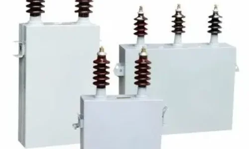
Quality matters significantly in power capacitor selection. Budget units from unknown manufacturers fail prematurely—sometimes creating safety hazards. Reputable brands with established track records justify their higher prices through longer service life and better reliability.
Wrapping Up the Calculation Process
Power capacitor sizing combines straightforward mathematics with practical engineering judgment. The basic formula provides reactive compensation requirements. Real-world considerations shape final equipment selection.
Getting this right saves money year after year. Getting it wrong creates ongoing problems that cost more than proper engineering would have. For significant installations, professional analysis pays for itself many times over through avoided mistakes and optimized performance.
The calculation marks the starting point, not the finish line. But without accurate numbers to begin with, everything else builds on a shaky foundation. If you want to know more about power capacitor, please read about What is the most popular power capacitor.
Frequently Asked Questions
What happens if a power capacitor is oversized for the application?
Oversized capacitors push power factor above 1.0 into leading territory. This causes voltage rises that can damage sensitive equipment. Some utilities also penalize leading power factor, negating expected savings. Additionally, excess capacitance increases risk of harmonic resonance problems. Proper sizing prevents these issues while still achieving correction goals.
How often should power capacitor calculations be revisited?
Recalculation makes sense whenever significant load changes occur—new equipment installations, production expansions, or major process modifications. Even without obvious changes, reviewing power factor performance annually helps catch gradual shifts. Utility bills often include power factor data that tracks trends over time.
Can power capacitor correction eliminate utility penalties completely?
In most cases, yes. Targeting power factor above the penalty threshold (typically 0.90 or 0.95 depending on utility) eliminates those specific charges. However, some utilities structure rates differently, with power factor affecting demand charges rather than applying direct penalties. Understanding the specific rate structure ensures correction targets match billing mechanics.