It is a scenario seen time and time again in industrial settings: a facility manager notices the electricity bill is creeping up due to reactive power penalties, so they order a solution. But once the equipment arrives, a confusing question arises. Where exactly does the device go? The physical location of a power factor correction capacitor is not just a matter of finding empty wall space; it fundamentally changes how effective the system is at reducing line losses and stabilizing voltage.
From an observational perspective, there isn’t a single “perfect” spot. It usually depends on the layout of the factory, the types of motors being used, and how much money is available for installation. The electrons don’t care about the budget, but the engineering team certainly does. Placing the capacitor too far upstream might save on utility penalties but leaves the internal wiring stressed, while placing it too deep in the system creates maintenance headaches.
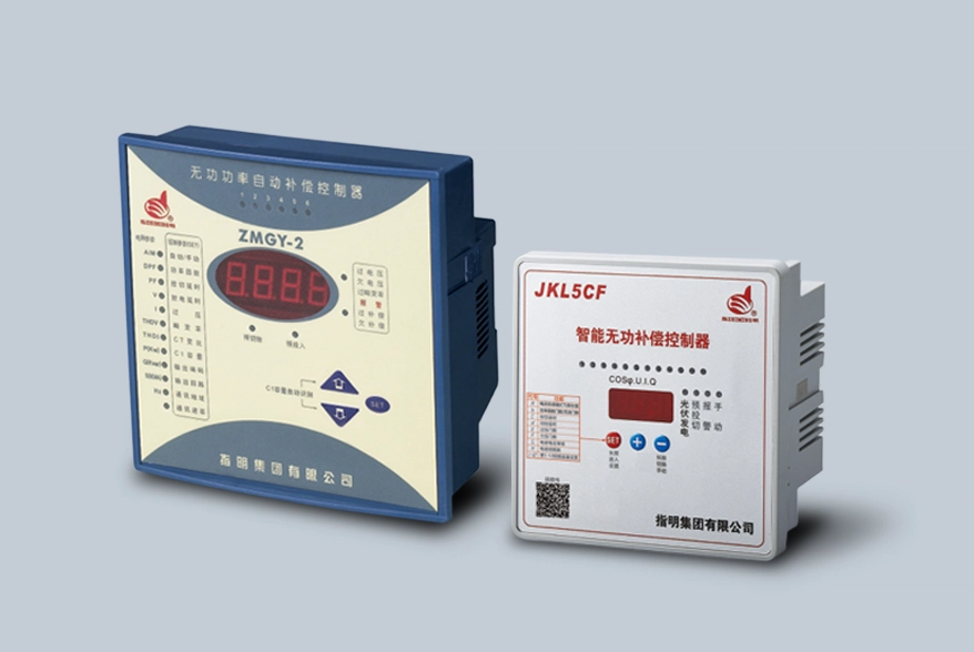
Table of Contents
Installing the Power Factor Correction Capacitor at Individual Loads
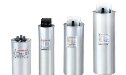
This method, often called “fixed compensation,” feels like the most technically pure approach. Ideally, you want to generate reactive power exactly where it is consumed. By installing a power factor correction capacitor directly at the terminals of an inductive load (like a large induction motor or a transformer), you are essentially cleaning up the current right at the source.
When you look at the schematics for heavy machinery, you often see the capacitor wired in parallel with the motor windings. The beauty of this setup is simplicity in operation. When the motor turns on, the capacitor turns on. When the motor shuts off, the capacitor cuts out. There is no need for complex controllers or switching logic.
- Benefits of this placement:
- It reduces current flow through the entire cable length leading to the motor.
- It reduces I²R losses (heat) in the cables and switchgear.
- It frees up capacity on the upstream transformer.
However, it is worth noting that this approach can get expensive quickly. If a factory has two hundred small motors, installing two hundred small capacitors is a logistical nightmare. It just isn’t practical for facilities with many small, scattered loads. It is generally reserved for large, constantly running motors where the ROI makes sense.
Group Placement Strategies for the Power Factor Correction Capacitor
Sometimes, the individual approach is just too granular. This is where group compensation comes into play. Imagine a workshop floor where several motors operate together—perhaps a conveyor belt system or a set of textile machines that always run in unison. In these cases, it makes little sense to treat them individually.
Engineers often connect a capacitor bank to a distribution board that serves that specific group of machines. In larger industrial facilities, this is typically the node where a high voltage power factor capacitor is installed to manage the collective inductance of the zone. It feels like a middle-ground solution. You aren’t compensating right at the motor, so the short cables between the board and the motors still carry reactive current, but the main feeder cable coming from the transformer is relieved of that burden.
This setup is frequent in scenarios where loads are intermittent but clustered. For instance, if a specific production line runs only during the day, the contactor for that distribution board can bring the capacitor online only when that section of the factory is energized. It saves on component wear and tear.
Centralized Power Factor Correction Capacitor Installation
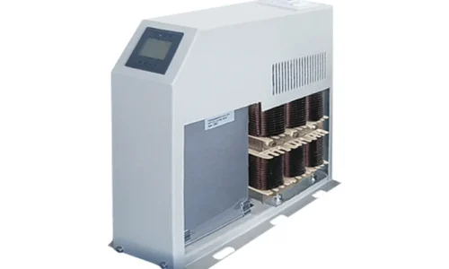
This is, by far, the most common configuration seen in modern commercial and industrial buildings. If you walk into the main electrical room of a large facility, you will likely see a large cabinet standing next to the main switchboard. This is the Automatic Power Factor Correction (APFC) panel.
In this scenario, the power factor correction capacitor (usually a bank of them) is connected to the main low-voltage busbar. The logic here is economic rather than purely technical. It is much cheaper to install one large automatic bank than fifty small ones.
- How it works:
- A controller monitors the total reactive power demand of the facility.
- It switches capacitors in and out in steps (stages) to maintain a target power factor (usually around 0.95 to 0.99).
- It handles the varying loads of the entire plant simultaneously.
Comparison of Placement Locations
| Placement Location | Cable Loss Reduction | Cost Complexity | Maintenance Effort | Typical Application |
|---|---|---|---|---|
| At Individual Load | High (Best) | High (Many units) | High | Large, continuous motors |
| Group / Zone | Medium | Medium | Medium | Clustered machinery |
| Central (Main Board) | Low (None for internal lines) | Low (One unit) | Low | General factories, offices |
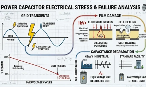
Safety Risks When Positioning a Power Factor Correction Capacitor
There is a slightly chaotic element to power factor correction that doesn’t get discussed enough: harmonics. You cannot simply stick a power factor correction capacitor anywhere and hope for the best. If the facility has a lot of non-linear loads—things like Variable Frequency Drives (VFDs), LED lighting drivers, or welding machines—the grid is likely dirty with harmonic currents.
If a capacitor is placed incorrectly in a high-harmonic environment without a detuning reactor (an inductor), it can create a resonance circuit. It’s a phenomenon that can cause the capacitor to overheat, bulge, or even fail catastrophically.
Resources
Wikipedia: Power Factor: This offers a comprehensive breakdown of the mathematical relationship between real, reactive, and apparent power. It also details the “beer analogy” often used to explain these concepts to non-engineers and covers the fundamental principles of linear vs. non-linear loads.
All About Circuits: Practical Power Factor Correction: This site provides detailed literature on the calculation side of things. It walks through the specific formulas needed to size a capacitor bank correctly and offers circuit diagrams that visualize the difference between parallel connection at the load versus the busbar.
FAQ
Can I install a power factor correction capacitor on a residential home?
Technically, yes, but it is rarely worth it. Residential meters typically measure active power (watts), not reactive power (VARs), so homeowners are not penalized for poor power factor. Installing one won’t significantly lower a home electricity bill unless the utility has a very specific penalty structure.
What happens if I put the capacitor before the main switch?
This is generally not allowed and is dangerous. The power factor correction capacitor should always be downstream of the main isolation switch and overcurrent protection. If it is placed before the switch, you cannot isolate it for maintenance, creating a severe shock hazard.
Will the capacitor save energy on the motor itself?
Not exactly. The motor requires the same amount of energy to do its work regardless of the capacitor. The savings come from reducing the losses (heat) in the cables feeding the motor. While the motor might run slightly cooler due to stable voltage, the primary savings are on the utility bill penalties and distribution losses.