Dealing with industrial electricity bills can sometimes feel like trying to read a foreign language. You see charges for things like “demand,” “usage,” and then this mysterious penalty for “reactive power.” It is frustrating to pay for energy that isn’t actually doing any useful work. This is where power factor correction comes into play, and specifically, where sizing the right power capacitor becomes a critical task for facility managers and electrical engineers.
It is not just about slapping a box on the wall and hoping for the best. There is a bit of math involved, but it doesn’t have to be overwhelming. Getting the calculation right ensures that your equipment runs cooler and your utility provider stops sending those angry letters about grid strain.
Table of Contents
Understanding the Basics Before Sizing a Power Capacitor
Before diving into the calculator or the formulas, it helps to understand what we are actually trying to fix. In alternating current (AC) systems, you have two types of power working together. You have the Real Power (kW), which is the stuff that actually turns the motor shaft or heats the oven. Then you have Reactive Power (kVAR), which creates the magnetic fields needed for inductive loads like motors and transformers.
Think of it like a glass of beer. The liquid is the Real Power—that is what you want. The foam is the Reactive Power. A little foam is necessary to keep the beer fresh, but if your glass is 50% foam, you aren’t getting your money’s worth. A power capacitor essentially acts as a localized foam reducer (or rather, a foam supplier), so the utility company only has to send you the liquid.
If you don’t have enough capacitance in the system, your Power Factor (the ratio of liquid to total volume) drops. A perfect score is 1.0. Most factories hover around 0.7 or 0.8 without correction, which is inefficient. The goal of calculating the size of the power capacitor is to determine exactly how much reactive power (kVAR) you need to inject to boost that number up to a target, usually around 0.95.
The Step-by-Step Calculation for Power Capacitor Sizing
So, how do you actually put a number on it? You generally need a few key pieces of data from your electrical bill or a power analyzer meter. It is basically a three-step process to find the required kVAR rating.
Step 1: Determine the Existing Power Factor
First, you need to know where you are starting. You can usually find this on your monthly utility bill, or you can measure it directly. Let’s say your facility is running at a Power Factor of 0.70.
Step 2: Set Your Target Power Factor
You usually don’t aim for a perfect 1.0 because it can get risky (more on that later). A target of 0.95 is the industry standard. It gets you out of the penalty zone without risking over-correction.
Step 3: Apply the Formula
The calculation determines the reactive power (kVAR) needed from the power capacitor. The formula relies on the tangent of the phase angles associated with your power factors.
The formula looks like this:
- kVAR = P (kW) × [tan(θ1) – tan(θ2)]
Where:
- P is your Real Power load in kW.
- tan(θ1) is the tangent of the angle for the existing power factor.
- tan(θ2) is the tangent of the angle for the target power factor.
It sounds complicated, but you are just finding the difference between what you have and what you want. Once you have that kVAR number, that is the size of the power capacitor bank you need to buy.
Using a Multiplier Table for Quick Power Capacitor Sizing
Let’s be honest, not everyone carries a scientific calculator around the factory floor to calculate tangents. In the real world, most people use a K-factor table. It simplifies the math into a single multiplier. You just find your current power factor on the left, your target on the top, and the table gives you a number.
Example: If you have a 100 kW load running at 0.70 power factor and you want to get to 0.95, you look at the table. The intersection of 0.70 and 0.95 is 0.691.
- 100 kW × 0.691 = 69.1 kVAR.
So, you would go out and look for a power capacitor bank rated for approximately 70 kVAR. It is much faster than doing the trigonometry manually.
Important Considerations Beyond the Math
Calculating the number is one thing; implementing it is another. There are nuances that the formula doesn’t capture. For instance, you generally don’t want to install a fixed power capacitor if your load fluctuates wildly. If your factory turns machines on and off all day, a fixed capacitor might provide too much correction when the machines are off, leading to something called a leading power factor. This can be just as bad as a lagging one, causing dangerous voltage rises.
Here are a few things to keep in mind:
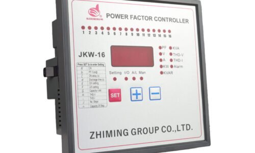
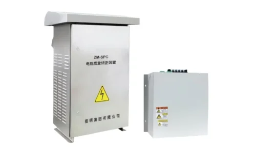
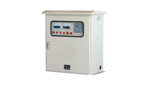
- Load Fluctuation: If your load varies, use an Automatic Power Factor Correction (APFC) panel. It switches capacitor steps in and out as needed.
- Harmonics: If you have a lot of Variable Frequency Drives (VFDs) or LED lighting, your system might be “dirty” with harmonics. A standard power capacitor can overheat or explode in these environments. You might need detuned reactors.
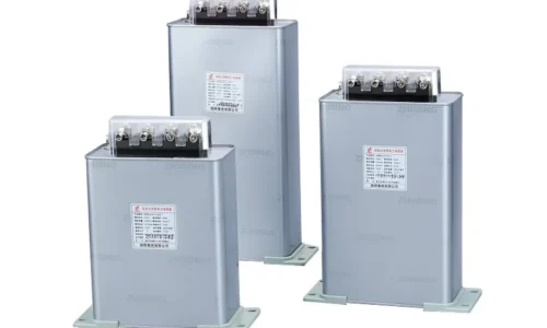
- Voltage Rating: Always ensure the voltage rating of the capacitor matches or slightly exceeds your system voltage.
It is also worth noting that the location matters. You can correct at the main switchboard (global correction) or right at the motor (local correction). Local correction is often more efficient for large, constantly running motors because it relieves the internal cabling of the reactive current, not just the utility grid. If you want to know more about power capacitor, please read How to test an industrial power capacitor.
FAQ
Can I correct my power factor to exactly 1.0?
Technically, yes, you can. However, it is usually not recommended. Aiming for exactly 1.0 (unity) puts you right on the edge. If the load drops slightly, your power capacitor might push the system into a “leading” power factor, which can cause voltage instability and trip breakers. Staying around 0.95 or 0.98 provides a safe buffer zone.
What happens if I oversize the power capacitor?
If you install a capacitor that is too big for the load, you get over-correction. This can raise the voltage level in your plant significantly. High voltage can burn out light bulbs, damage sensitive electronics, and even cause the capacitor itself to fail prematurely. It is better to be slightly under the target than significantly over it.
How do harmonics affect my calculation?
The basic kVAR calculation doesn’t change, but the equipment selection does. Standard capacitors act like sinks for high-frequency harmonic currents, which can cause them to overheat. If your facility has significant harmonic distortion, you need to buy a power capacitor equipped with harmonic blocking reactors (often called detuned capacitors). You might need a professional power quality analysis to determine if this is necessary.