Power factor correction sounds technical, and honestly, it is. But the basic idea isn’t too complicated. Electrical systems draw more current than they actually need when power factor drops below ideal levels. This wastes energy, increases utility bills, and can even trigger penalty charges from power companies. Installing a power capacitor helps fix this problem—though choosing the right one requires some thought.
The selection process involves more than just picking something off a shelf. Capacitor sizing, voltage ratings, installation type, and environmental conditions all play into the decision. Getting it wrong means either inadequate correction or, worse, equipment damage. Getting it right means lower bills and a more efficient electrical system overall.
Table of Contents
Understanding Why Power Capacitor Selection Matters
Most industrial and commercial facilities have inductive loads—motors, transformers, fluorescent lighting, that sort of thing. These loads cause current to lag behind voltage, creating what’s called reactive power. The utility still has to supply this reactive power even though it doesn’t do useful work. That’s where the inefficiency comes from.
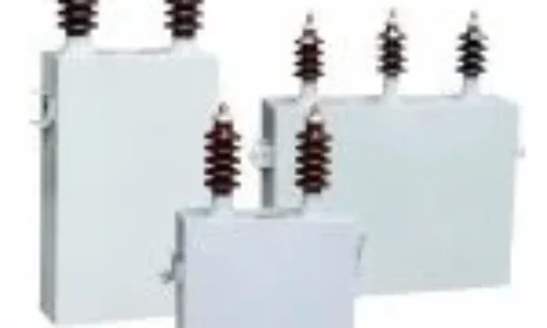
A power capacitor provides leading reactive power that offsets the lagging reactive power from inductive loads. The net effect is improved power factor, reduced current draw, and lower losses throughout the system. It sounds straightforward enough, but the details matter quite a bit in practice.
Selecting an undersized capacitor means partial correction at best. Oversizing creates its own problems—potential overvoltage conditions and wasted capital. The goal is matching capacitor ratings to actual system requirements, which requires some calculation and consideration of operating conditions.
Key Factors When Choosing a Power Capacitor
Calculating Required kVAR
The starting point for any power capacitor selection is determining how much reactive power compensation the system needs. This typically involves:
- Measuring or calculating current power factor
- Identifying target power factor (usually 0.95 or higher)
- Determining total kW load
- Using power factor correction tables or formulas to find required kVAR
The formula looks something like this: Required kVAR = kW × (tan θ1 – tan θ2), where θ1 and θ2 represent the angles corresponding to existing and target power factors respectively. Most engineers use lookup tables rather than calculating tangent values manually—it’s faster and less error-prone.
Voltage Rating Considerations
Capacitors must be rated for the system voltage where they’ll be installed. But there’s a catch—voltage at the capacitor terminals often exceeds nominal system voltage, especially during light load conditions. Selecting a power capacitor rated 10% above nominal voltage provides necessary margin.
Common voltage ratings include:
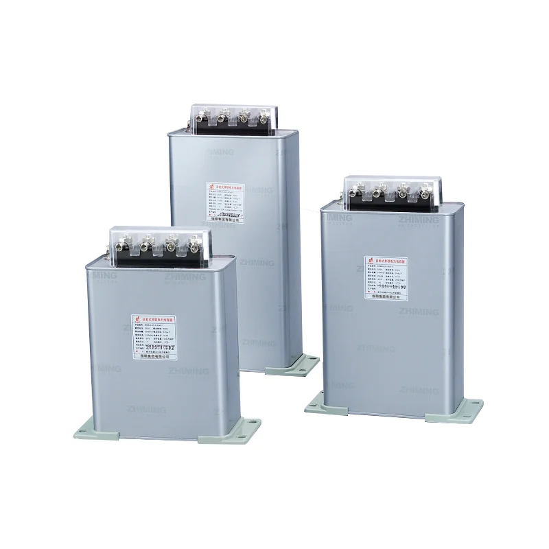
- 240V for light commercial applications
- 480V for typical industrial systems
- 600V for heavier industrial use
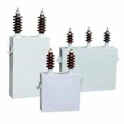
- Medium voltage ratings (2.4kV, 4.16kV, etc.) for larger facilities requiring high voltage power capacitor solutions
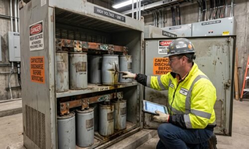
For facilities operating at these elevated levels, a high voltage power capacitor demands additional safety considerations and specialized installation protocols compared to standard low voltage units.
Single vs. Automatic Capacitor Banks
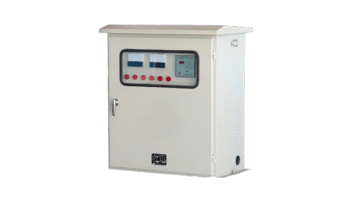
For facilities with relatively constant loads, fixed capacitor installations work fine. The capacitor stays connected continuously, providing steady correction. Simple and cost-effective.
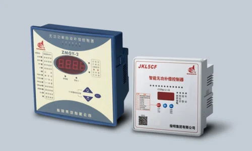
Variable loads present more complexity. A facility where motors cycle on and off throughout the day needs correction that adjusts accordingly. Automatic capacitor banks use controllers that switch capacitor stages in and out based on real-time power factor measurements. More expensive upfront, but they prevent overcorrection during light load periods.
Power Capacitor Specifications to Evaluate
| Specification | Why It Matters | Typical Range |
|---|---|---|
| Capacitance (kVAR) | Determines correction capability | 5-200+ kVAR per unit |
| Voltage Rating | Must exceed system voltage | 240V to 15kV |
| Frequency | Must match system frequency | 50Hz or 60Hz |
| Temperature Range | Affects lifespan and reliability | -25°C to +55°C typical |
| Discharge Resistor | Safety requirement | Built-in or external |
Installation Location for Power Capacitor Units
Where capacitors get installed affects their effectiveness. Three basic approaches exist:
- Load-side correction – Capacitors installed at individual motors or loads. Most effective electrically but higher installation cost.
- Distribution-level correction – Capacitors at distribution panels serving multiple loads. Good balance of effectiveness and cost.
- Main service correction – Capacitors at the main electrical service entrance. Lowest cost but least effective for reducing losses within the facility.
Many facilities use a combination approach—fixed capacitors at major motors plus an automatic bank at the main service.
Harmonic Considerations When Selecting Power Capacitor Equipment
Modern facilities often have significant harmonic distortion from variable frequency drives, LED lighting, computers, and similar nonlinear loads. Standard power capacitor installations can actually amplify harmonics under certain conditions, causing resonance problems.
Systems with substantial harmonic content (typically above 20% THD) may require detuned reactors in series with capacitors. These reactors shift the resonant frequency away from common harmonic frequencies, preventing amplification. It adds cost but avoids potentially serious problems.
FAQ
What happens if a power capacitor is oversized for the application?
Oversizing leads to leading power factor, which can be just as problematic as lagging power factor. Voltage rise occurs, potentially damaging sensitive equipment. Some utilities penalize leading power factor as well. Additionally, the excess capacitance represents wasted investment that provides no benefit.
How long does a typical power capacitor last?
Quality capacitors from reputable manufacturers typically last 10-15 years under normal operating conditions. High ambient temperatures, voltage transients, and harmonic distortion all shorten lifespan. Capacitors in automatic banks that switch frequently may experience shorter service life due to switching stress.
Can power capacitors be installed without professional help?
Technically possible for someone with electrical knowledge, but generally not recommended. Power capacitor installation involves working with potentially dangerous voltages and currents. Improper installation can damage equipment, create safety hazards, or result in inadequate correction. Licensed electricians familiar with power factor correction should handle installation in most cases.