Capacitor banks show up in almost every corner of electrical infrastructure — from massive utility substations to compact panels inside manufacturing plants. Their uses extend across so many applications that it would be difficult to find any modern power system operating entirely without them.
But what exactly are they used for? The short answer covers power factor correction, voltage support, harmonic filtering, and energy storage. The longer answer gets more interesting because each application brings its own engineering challenges and practical benefits.
For anyone evaluating whether a capacitor bank makes sense for their facility or system, understanding the full range of uses helps identify which applications deliver the most value.

Table of Contents
Industrial Use of a Capacitor Bank for Power Factor Correction
Why Industries Need Power Factor Correction
Industrial facilities consume enormous amounts of reactive power. Motors, compressors, welding machines, induction furnaces — all of these draw reactive current to maintain magnetic fields required for operation. The reactive current doesn’t produce useful output but still loads the electrical system.
Poor power factor resulting from excessive reactive demand creates tangible problems:
- Utility penalties that increase monthly electricity costs
- Higher current in cables and switchgear
- Increased transformer loading and losses
- Voltage drop at equipment terminals
- Reduced available capacity for productive loads
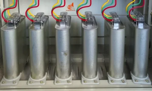
A capacitor bank installed at an industrial facility generates reactive power locally. This offsets what inductive loads demand, reducing the reactive burden flowing from the utility source.
Practical Implementation
Correction Level | Location | Advantages | Best Suited For |
Individual | At each motor | Maximum loss reduction, best voltage support | Large motors above 50 HP |
Group | Motor control centers | Good loss reduction, moderate cost | Clusters of medium motors |
Central | Main distribution board | Lowest cost, simplest maintenance | General facility correction |
Combination | Multiple levels | Balanced performance and cost | Complex industrial plants |
Utility Use of Capacitor Bank Systems for Voltage Regulation
Maintaining Grid Voltage Quality
Utilities face a constant challenge — keeping voltage within acceptable limits across vast networks serving variable loads. Voltage drops when demand increases and rises when demand falls. Long distribution lines make the problem worse.
Capacitor bank installations at strategic locations along utility networks provide reactive power support that stabilizes voltage. The effect is particularly noticeable on rural feeders stretching many miles from substations.
Common utility capacitor bank deployments include:
- Substation capacitor banks for bulk reactive compensation
- Pole-mounted units along distribution feeders
- Switched banks at critical voltage-sensitive locations
- Series capacitor banks on long transmission lines
Demand-Responsive Switching
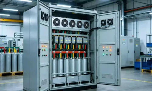
Modern utility capacitor bank installations often include automatic controls that switch capacity based on system conditions. During heavy loading periods, all available capacitor bank steps energize to support voltage. During light loading — late night hours, for instance — banks switch off to prevent voltage from rising too high.
This demand-responsive operation maximizes benefit while avoiding the overcorrection problems that fixed installations sometimes create. The controls respond to voltage, current, reactive power, or time-based schedules depending on system characteristics and utility preferences.

Specialized Uses of Capacitor Bank Technology
Harmonic Filtering Applications
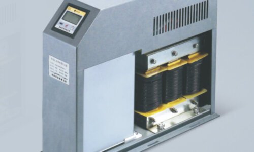
In systems with heavy nonlinear loads, capacitor bank assemblies serve as core components of harmonic filter installations. When paired with precisely sized reactors, they create tuned circuits that absorb harmonic currents at specific frequencies.
This use has become increasingly relevant as power electronics proliferate — variable frequency drives, LED lighting systems, data center power supplies — all generating harmonics that distort voltage waveforms. Without filtering, these harmonics cause overheating, interference, and equipment malfunctions.
A harmonic filter capacitor bank does double duty. It provides power factor correction at fundamental frequency while absorbing harmful harmonics. Clever engineering, really.
Energy Storage and Pulsed Power
Some applications use capacitor bank systems purely for energy storage purposes. The characteristics suit specific needs that batteries handle poorly:
- Extremely rapid discharge capability
- Very high cycle life without degradation
- No chemical processes limiting charge rate
- Precise energy delivery control
Applications range from scientific research equipment requiring enormous brief power pulses to industrial welding systems and electromagnetic forming machines. Electric vehicle fast-charging stations also incorporate capacitor bank technology to buffer grid demand during high-power charging events.
Motor Starting Support
Large motors draw several times their normal current during starting. This inrush stresses the electrical system and causes temporary voltage dips that affect nearby equipment. Capacitor bank systems sized for motor starting provide reactive power support during the critical startup period, reducing voltage sag and easing the impact on other connected loads.
This use is common in water treatment plants, mining operations, and oil field installations where large pumps and compressors start frequently. If you want to know more about capacitor bank, please read What is a capacitor bank.
FAQ
Can a capacitor bank be used for both power factor correction and harmonic filtering?
Yes, and this dual-purpose configuration is actually quite common in industrial settings. Detuned capacitor bank systems use series reactors typically tuned to around 189 Hz (4.7th harmonic) or 134 Hz (3.78th harmonic depending on system) to prevent resonance while still providing effective power factor correction. The reactor shifts the natural resonant frequency away from common harmonic orders, protecting the capacitor bank from harmonic overcurrent.
What size capacitor bank does a typical factory need?
Sizing depends entirely on facility load characteristics and target power factor. A rough estimate starts with total kW demand and current power factor. For example, a 1,000 kW facility operating at 0.75 power factor would need approximately 550 kVAR of capacitor bank capacity to reach 0.95. But nameplate-based estimates frequently miss the mark because actual operating conditions differ from rated values. Proper sizing requires power quality measurement over representative operating periods — ideally capturing both peak and minimum load conditions.
Is a capacitor bank safe to operate around personnel?
Modern capacitor bank installations include comprehensive safety features and are generally safe when properly designed, installed, and maintained. Key safety provisions include discharge resistors that bleed stored energy after de-energization, overcurrent protection through fuses and circuit breakers, enclosures preventing accidental contact, and pressure-relief features on individual capacitor units. However, capacitor banks store electrical energy that remains dangerous even after disconnection — discharge time typically requires several minutes.