Walk through any industrial facility or utility substation and there’s a good chance you’ll pass right by capacitor bank installations without realizing their importance. These unassuming electrical assemblies — often housed in metal enclosures or mounted on utility poles — play a critical role in how power systems operate efficiently.
A capacitor bank is essentially a group of capacitor units connected together to achieve electrical characteristics that individual capacitors couldn’t provide alone. The arrangement might involve series connections, parallel connections, or combinations of both depending on the voltage and reactive power requirements of the specific application.
The concept sounds straightforward enough. But understanding what a capacitor bank actually does — and why facilities invest in them — requires looking at how electrical power systems work and where capacitor banks fit into that picture.
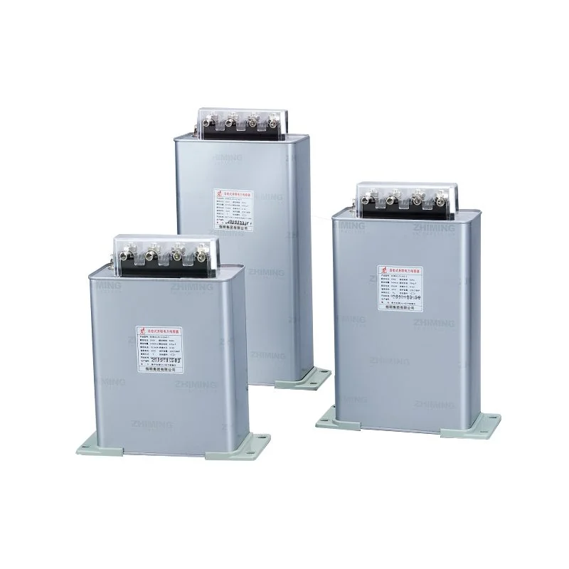
Table of Contents
Understanding What a Capacitor Bank Does
The Basic Function
At its core, a capacitor bank stores and releases electrical energy. In AC power systems — which covers most applications — this energy exchange happens continuously as voltage alternates. The capacitor bank absorbs energy during one part of the cycle and returns it during another.
This behavior makes capacitor banks uniquely useful for reactive power compensation. Most industrial loads, particularly motors, draw reactive power from the supply system. This reactive current doesn’t perform useful work but still flows through cables, transformers, and other equipment, creating losses and consuming capacity.
A capacitor bank generates reactive power locally. Instead of reactive current flowing all the way from the utility source, the capacitor bank supplies it right at the facility. The result is:
- Reduced current flow through upstream equipment
- Lower electrical losses throughout the system
- Improved voltage regulation
- Released capacity for additional loads
Power Factor Correction Explained
Power factor measures how effectively electrical power converts to useful work. A power factor of 1.0 means perfect efficiency — all current performs productive work. Lower power factors indicate reactive current flowing alongside working current.
Most facilities operate somewhere between 0.70 and 0.95 power factor without correction. Utilities penalize poor power factor through rate structures, and the internal inefficiencies cost money regardless of utility charges.
Installing a capacitor bank improves power factor by offsetting the reactive power demand of inductive loads. A facility with 0.75 power factor might improve to 0.95 or higher with proper capacitor bank installation — eliminating penalties and reducing internal losses substantially.
Components of a Capacitor Bank System
Main Elements
A complete capacitor bank installation involves more than just capacitors. The system typically includes several components working together:
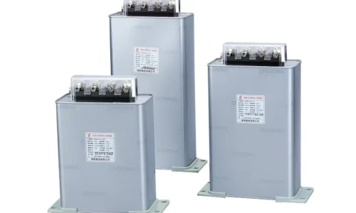
- Capacitor units — the actual energy storage elements
- Switching devices — contactors or circuit breakers for control
- Protective fuses — individual unit or group protection
- Discharge resistors — safely drain stored energy when de-energized
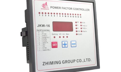
- Control systems — automatic or manual switching logic
- Enclosures — physical protection and safety barriers
Larger installations add complexity with current-limiting reactors for inrush control, harmonic filters for distorted environments, and sophisticated controllers that optimize capacitor switching based on real-time system conditions.
Configuration Options
Configuration | Voltage Rating | Typical Application | Complexity |
Single unit | Low voltage | Small motor correction | Minimal |
Parallel bank | Low voltage | Industrial distribution | Low |
Series-parallel | Medium voltage | Substation installation | Moderate |
Double-star | High voltage | Transmission systems | High |
H-bridge | High voltage | Utility substations | High |
Types of Capacitor Bank Systems
Fixed Capacitor Banks
The simplest type stays connected continuously. Fixed capacitor banks suit applications with steady, predictable reactive power demand — constant motor loads, for instance, where compensation needs don’t change much throughout operation.
Advantages of fixed banks include:
- Lower initial cost
- Simpler installation
- Reduced maintenance requirements
- No switching transients during operation
- Higher reliability from fewer components
The limitation is obvious — they can’t adapt to changing conditions. If load varies significantly, a fixed capacitor bank either under-compensates during heavy loading or over-compensates during light loading.
Automatic Switched Capacitor Banks
Automatic capacitor bank systems add intelligence. Controllers monitor power factor, reactive power, or other parameters and switch capacitor steps in or out as conditions change.
These systems match compensation to actual demand throughout operating cycles. A factory might need full compensation during production hours but almost none during idle periods. Automatic switching handles this variation without operator intervention.
The tradeoffs involve increased complexity, higher cost, and maintenance requirements for switching components. Contactors wear out. Controllers need calibration. But for variable loads, the benefits typically justify the investment.
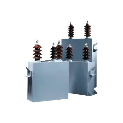
Thyristor-Switched Capacitor Banks
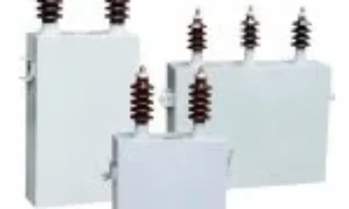
For applications requiring fast, precise, and frequent switching of high voltage capacitor bank systems, thyristor-controlled solutions offer distinct advantages over mechanical contactors. Solid-state switching eliminates contactor wear, reduces switching transients, and enables response times measured in milliseconds rather than cycles.
This technology is well-suited for controlling high voltage capacitor banks. Utility applications, such as static VAR compensators, often use thyristor-switched capacitor banks as part of larger reactive power control systems. Industrial applications with highly variable, sensitive, or demanding loads—where rapid and reliable adjustment of a high voltage capacitor bank is critical—also benefit significantly from this solid-state approach.
Where Capacitor Bank Installations Are Used
Industrial Applications
Manufacturing facilities represent the largest market for capacitor bank systems. Motors dominate industrial electrical loads, and motors draw reactive power. Power factor correction through capacitor bank installation reduces utility costs and improves electrical system performance.
Common industrial applications include:
- Manufacturing plants with heavy motor loads
- Water treatment and pumping stations
- Mining operations
- Steel mills and foundries
- Chemical processing facilities
The financial payback from utility penalty elimination typically justifies capacitor bank investment within one to three years. Continued savings accumulate indefinitely after that.
Utility and Transmission Systems
Electric utilities deploy capacitor banks throughout transmission and distribution networks. The scale differs dramatically from industrial applications — utility capacitor bank installations might provide hundreds of megavars of reactive compensation.
These installations support voltage regulation, increase transmission capacity, reduce system losses, and improve overall grid efficiency. Without widespread reactive power compensation, electrical grids would operate significantly less efficiently and require much larger infrastructure investments.
FAQ
How much does a capacitor bank cost?
Capacitor bank costs vary widely based on voltage level, reactive power rating, and control sophistication. Small low-voltage fixed banks might cost a few hundred dollars for basic motor correction. Industrial automatic switched systems typically range from several thousand to tens of thousands of dollars depending on size. Medium and high voltage installations for utility applications can reach hundreds of thousands of dollars for large substations. Installation costs add significantly to equipment expense — sometimes equaling or exceeding the hardware cost for complex projects.
How long does a capacitor bank last?
Properly designed and operated capacitor bank installations typically provide 15-20 years of service life. Actual longevity depends heavily on operating conditions — ambient temperature, voltage stress relative to rating, harmonic exposure, and switching frequency all affect lifespan. Capacitors gradually degrade over time, losing capacitance and developing increased internal losses. Periodic testing identifies degradation before it causes problems. Switching components in automatic banks often require replacement before the capacitors themselves fail. Well-maintained installations with moderate operating conditions can exceed 20 years, while harsh environments or inadequate maintenance might limit life to 10-12 years.
Can a capacitor bank cause problems?
Yes, improperly applied capacitor bank installations can create problems rather than solve them. Common issues include harmonic resonance when capacitor banks interact with system inductance at harmonic frequencies, potentially amplifying distortion dramatically. Switching transients from capacitor bank energization can disturb sensitive equipment. Overcorrection from excessive capacitor bank rating causes leading power factor, which some utilities penalize and which can create voltage rise issues.