Ever looked at an electricity bill and noticed a “power factor penalty”? That’s when things get interesting. A power factor controller is that small box on the wall of many industrial electrical rooms – the one quietly doing its job while everyone walks past. But how exactly does it work? And why should anyone care?
This isn’t about perfect engineering formulas. It’s more like watching a smart assistant adjust things behind the scenes, sometimes a little late, sometimes surprisingly quick.
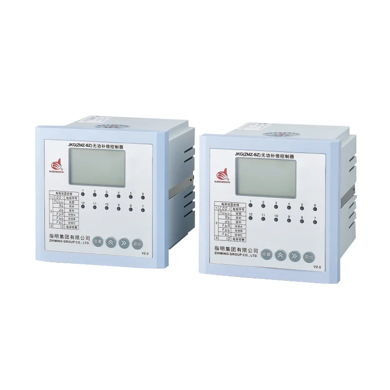
Table of Contents
What a Power Factor Controller Actually Does
To understand the controller, first think about power factor itself. In simple terms, it’s the ratio between real power (what does useful work, like spinning a motor) and apparent power (what the grid supplies). A low power factor means there’s too much “reactive power” – think of it as sloshing water in a pipe that doesn’t really go anywhere.
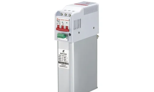
A power factor controller doesn’t generate power. It doesn’t fix bad wiring overnight. What it does is monitor the network continuously, then decide when to connect or disconnect capacitor banks (or sometimes reactors). Capacitors cancel out the lagging effect of inductive loads like motors, transformers, and welding machines.
Seen from the side, it’s almost like a traffic cop. When too many inductive devices start up, the controller sees the power factor dropping below a set threshold – say 0.92 – and signals contactors to bring in capacitors. When the load decreases, it switches them off again. That’s the basic loop.
Step by Step – How the Controller Makes Decisions
Inside the controller, there’s a microprocessor (some older ones use analog circuits, but those are fading). It measures voltage and current waveforms multiple times per second. From that, it calculates the phase shift between them. That phase shift tells you exactly how bad the power factor is.
Here’s a rough sequence of what happens:
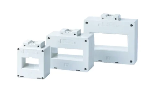
The controller samples the grid’s voltage and current through CTs (current transformers) and PTs.
It computes the real-time power factor, along with active and reactive power.
If reactive power exceeds a programmed limit, it triggers a “step” – connecting one stage of capacitors.
After a short delay (to let transients settle), it rechecks. If still low, another step connects.
When the power factor goes above target (over-correction), it disconnects steps in reverse order.
That delay part is interesting. Some controllers are aggressive – they switch within a second. Others are more relaxed, maybe 5 to 10 seconds between steps. There’s no single “correct” speed; it depends on how fast the load changes. A rock crusher? Quick response needed. A ventilation fan? Slower is fine.
The Hunting Problem Nobody Talks About
Ever seen a controller that keeps flipping capacitors on and off every few seconds? That’s called “hunting.” It happens when the target power factor is set too tight, or the load is fluctuating right around the threshold. From an observational point, it’s annoying – the contactors click constantly, and capacitors wear out faster.
Some controllers have a built-in “switching differential” or hysteresis to avoid this. Others don’t. So a cheap controller might cause more trouble than it solves. That’s something electricians notice over time.

Where You’ll Find Power Factor Controllers (Real Examples)
Walk into any medium-sized manufacturing plant – plastics, metalworking, food processing – and there’s probably a controller mounted inside a distribution panel. Often it has a small LCD display showing PF, voltage, current, and maybe harmonics.
A few typical scenarios:
Lift irrigation pumps: Large motors running for hours. Power factor can drop to 0.6 without correction. A controller brings it back to 0.95.
Office buildings with many air conditioners: Not as critical, but some utilities charge penalties below 0.9.
Welding shops: Extremely fluctuating loads. Only a fast thyristor-based controller can keep up. Even then, sometimes it lags.
And here’s a curious thing: sometimes the controller works perfectly but the power factor remains poor because of harmonic distortion. The controller sees distorted waveforms and misinterprets the phase angle. That’s when an experienced technician adds a detuned reactor in front of the capacitors. Not the controller’s fault – just the messy reality of modern electronics. If you want to know more about power factor controller, please read What is a power factor controller.
FAQ
Does a power factor controller save energy directly?
Not exactly. It reduces reactive current in the wires, which lowers resistive losses (I²R) in cables and transformers. So it saves a little energy – maybe 1% to 3% in most cases. The real saving comes from avoiding utility penalties and freeing up capacity. Some people think it magically cuts the kWh bill; that’s a myth unless the wiring is very old or undersized.
Can a power factor controller work with a generator instead of the grid?
Yes, but it’s trickier. Generators have higher internal impedance and react differently to capacitor switching. Some controllers have a special “generator mode” that slows down switching or uses smaller step sizes. Without that, the generator might hunt or even trip on overvoltage. Seen that happen once – not pretty.
How many steps or stages should a good controller have?
Depends on the load variation. For a stable load, 4 to 6 steps are enough. For highly variable loads, 8 to 12 steps give finer resolution. But more steps also mean more contactors and capacitors – higher cost and more things to fail. A common observation: many installations use 6-step controllers, but only 4 steps ever actually switch because the load never demands more.