Table of Contents
The Basic Idea Behind a Power Factor Controller
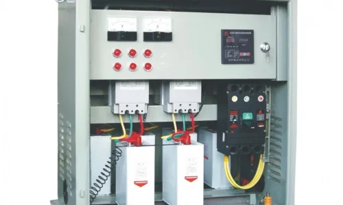
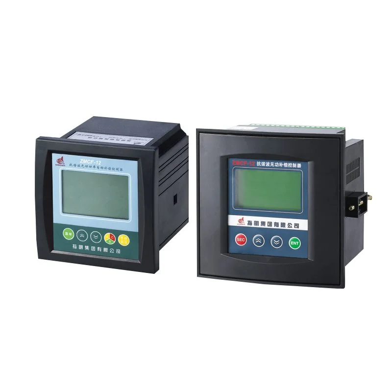
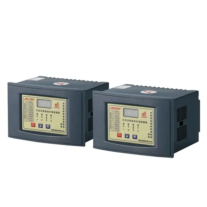
Walk into any industrial facility or large commercial building. Behind the main electrical panel, there is often a metal enclosure with a small digital display and a row of contactors. That device? It’s a power factor controller. And it does one simple thing: it keeps the electrical system running efficiently by switching capacitor banks on and off automatically.
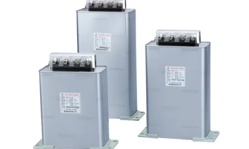
The name sounds technical. But the concept is not that complicated. Electrical equipment like motors, transformers, and fluorescent lighting create a situation where not all the power drawn from the grid gets used effectively. Some of it just sloshes back and forth. That wasted portion is called reactive power. A power factor controller measures how bad that waste is (the power factor number) and then decides when to bring in capacitors to cancel out the waste. It is like a thermostat, but for electrical efficiency instead of temperature.
Why a Power Factor Controller Matters for Your Electric Bill
The Penalty Problem
Utility companies dislike reactive power. It takes up capacity on their lines without generating revenue. So most commercial and industrial customers get billed not just for the power they actually use (real power, measured in kilowatt-hours) but also for how low their power factor drops. A power factor below 0.9 often triggers a penalty. Below 0.8? The surcharge gets painful.
A power factor controller prevents that. By watching the power factor in real time—maybe every few seconds or minutes depending on the model—it brings in just enough capacitors to push the number back above the penalty threshold. Some facilities have cut their monthly utility bills by 10 to 15 percent simply by adding one of these controllers. That is real money, especially for factories running 24/7.
The Observational View
From a field technician’s perspective, a building without a power factor controller often shows strange symptoms. Transformers run hotter than they should. Cables feel warm to the touch even under moderate loads. The main breaker trips occasionally for no obvious reason. These are signs of reactive power circulating unnecessarily. Once a controller is installed and tuned, those symptoms usually disappear. The system just runs smoother. It is one of those things that is hard to appreciate until you see the before-and-after difference.
How a Power Factor Controller Actually Works
The internal logic is surprisingly straightforward. A power factor controller typically has three main parts:
A measurement input that reads voltage and current from the main bus
A microprocessor that calculates the real-time power factor
A set of relay outputs that switch capacitor steps on and off
The controller compares the measured power factor to a target value (usually set between 0.92 and 0.98). If the measured number is too low, it switches on one capacitor step. It waits a few seconds, measures again, and decides whether another step is needed. This cycle repeats continuously. Some controllers use a “hunting” algorithm to avoid switching back and forth constantly, which would wear out the contactors.
Where You Typically See a Power Factor Controller
Industrial Settings
Factories with many motors—think conveyors, compressors, injection molding machines—have highly variable power factors. A power factor controller here is almost mandatory. It switches capacitors rapidly as machines start and stop.
Commercial Buildings
Large office towers, hospitals, and shopping malls also benefit, though the changes happen more slowly. HVAC systems and elevators create the reactive load. A power factor controller in these settings might only switch a few times per hour, but the savings still add up.
Renewable Energy Sites
Solar farms and wind installations sometimes use power factor controllers to maintain grid compliance. The grid operator may require a specific power factor at the point of interconnection. The controller adjusts inverter settings or, in systems with split-phase configurations, a split-phase capacitor controller switches capacitor banks to meet that requirement.
Things That Can Go Wrong (From Experience)
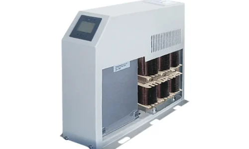
No device is perfect. A power factor controller can misbehave under certain conditions. Harmonic distortion from variable frequency drives or switching power supplies confuses some older controllers. They see distorted waveforms and calculate the wrong power factor. The result? They switch capacitors incorrectly, sometimes making the situation worse.
Another real-world issue: failed contactors. The controller sends a signal, but the mechanical contactor does not close. The controller keeps trying, but the power factor stays low. An observant technician notices that the controller shows all steps engaged yet the power factor remains poor. That is a dead giveaway that a contactor or a capacitor has failed. Regular maintenance (checking contactor operation and capacitor health) keeps the system reliable.
FAQ
Can a power factor controller save energy on its own?
No, it does not directly reduce the kilowatt-hours consumed by motors or lights. What it does is reduce the current flowing through cables and transformers, which lowers resistive losses (I²R losses). Those losses are real energy savings, typically in the range of 1 to 3 percent of total consumption. The bigger saving comes from avoiding utility penalties.
How long does a power factor controller last?
The electronics inside a power factor controller can last 10 to 15 years easily. The contactors that actually switch the capacitors wear out faster—maybe 5 to 8 years depending on switching frequency. Capacitors themselves degrade over time and may need replacement every 8 to 10 years. The controller is often the longest-lived part of the system.
Can I install a power factor controller myself?
Probably not. Working with capacitor banks involves high voltages even when the main supply is off—capacitors store energy. A licensed electrician or a power quality specialist should handle the installation. The controller itself requires programming with the correct CT ratio, target power factor, and step configuration. Getting those settings wrong leads to poor performance or equipment damage.