Table of Contents
The Connection Between a Capacitor Bank and Power Factor
Electricity bills keep climbing. For industrial and commercial facilities, power factor penalties often add insult to injury—extra charges for using power inefficiently. The solution sitting in countless electrical rooms? A capacitor bank.
This technology has been around for decades. Nothing revolutionary about it. Yet many facility managers still don’t fully understand how these devices actually work to improve power factor. The concept seems abstract until someone explains the underlying physics in practical terms.
Understanding this relationship helps justify investment decisions and optimize installations for maximum benefit.
What Power Factor Actually Means in Electrical Systems
Real Power Versus Reactive Power
Electrical loads consume power in two forms. Real power—measured in kilowatts—does actual work. It turns motors, produces light, generates heat. This is what facilities actually need.
Reactive power is different. Measured in kVAR, it flows back and forth between source and load without producing useful output. Motors, transformers, and fluorescent lighting require reactive power to establish magnetic fields. They can’t function without it.
The problem? Reactive power consumes system capacity without contributing to productive output.
Power Factor Defined
Power factor represents the ratio between real power and apparent power (the combination of real and reactive). A power factor of 1.0 means all power delivered is being used productively. Perfectly efficient.
Most industrial facilities operate somewhere around 0.75-0.85 naturally. Motors and other inductive loads drag the number down. Utilities don’t appreciate this—it forces them to generate and transmit more current than facilities actually consume usefully.
How a Capacitor Bank Corrects Poor Power Factor
The Compensation Principle
Inductive loads (motors, transformers) cause current to lag behind voltage. Capacitive loads cause current to lead voltage. When combined appropriately, these effects cancel each other.
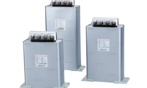
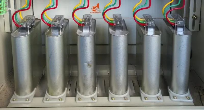
A capacitor bank supplies reactive power locally. Instead of drawing reactive current from the utility supply through miles of transmission lines, equipment draws it from capacitors installed nearby—sometimes in the same room.
The result:
- Current drawn from utility decreases
- Power factor improves toward unity
- System losses reduce
- Capacity gets freed up
It’s elegant really. The physics just works.
Practical Example
Consider a manufacturing plant drawing 500 kW of real power at 0.75 power factor. The apparent power equals 667 kVA, and reactive power reaches 441 kVAR.
Installing a capacitor bank rated for 300 kVAR changes everything. Reactive demand from the utility drops to 141 kVAR. Power factor improves to approximately 0.96. Apparent power drops to 520 kVA.
Parameter | Before Correction | After 300 kVAR Capacitor Bank |
Real Power | 500 kW | 500 kW |
Reactive Power | 441 kVAR | 141 kVAR |
Apparent Power | 667 kVA | 520 kVA |
Power Factor | 0.75 | 0.96 |
Current Draw | Higher | 22% Lower |
Types of Capacitor Bank Installations for Power Factor Improvement
Fixed Compensation
The simplest approach. A fixed capacitor bank provides constant reactive power regardless of load variations. Works well when:
- Loads remain relatively stable
- Minimum reactive demand stays consistent
- Budget constraints limit options
- Simplicity matters more than optimization
Fixed installations cost less upfront but can overcorrect during light load periods—potentially causing leading power factor issues.
Automatic Compensation
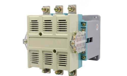
More sophisticated. Automatic capacitor bank systems use controllers that monitor power factor continuously. They switch capacitor stages in and out as loads change.
Benefits include:
- Consistent power factor across varying conditions
- No overcorrection during light loads
- Better optimization of correction level
- Reduced risk of resonance issues
The controller measures reactive demand and adjusts compensation accordingly. Some modern controllers even adapt to harmonic conditions.
Individual Versus Central Correction
Location matters too. Central correction places the capacitor bank at the main distribution panel. It improves power factor seen by the utility but doesn’t reduce losses within the facility.
Individual correction—capacitors at each motor or load—maximizes internal efficiency by reducing current throughout the distribution system. More expensive and complex, but technically superior.
Many facilities use hybrid approaches. Central correction handles baseline needs while individual correction addresses large loads.
Benefits Beyond Power Factor When Using a Capacitor Bank
Released System Capacity
Lower current means cables, transformers, and switchgear carry less load. This releases capacity for additional equipment without infrastructure upgrades. Sometimes the freed capacity alone justifies the investment.
Reduced Losses
Current flowing through conductors produces heat—wasted energy. Since a capacitor bank reduces total current, losses decrease throughout the system. Cables run cooler. Transformers operate more efficiently.
Improved Voltage
Excessive reactive current contributes to voltage drop. With compensation in place, voltage at load terminals improves. Motors run better. Sensitive equipment operates more reliably.
Sizing Considerations for Effective Power Factor Improvement
Target Power Factor
Most facilities aim for 0.95-0.98 after correction. Higher than 0.98 offers diminishing returns. Some utilities penalize leading power factor, so overcorrection carries risks.
Calculation Method
The basic approach involves:
- Measure existing real power demand
- Measure existing power factor
- Determine target power factor
- Calculate required kVAR using standard formulas or tables
Proper sizing also accounts for load variations, future expansion, and harmonic conditions. A capacitor bank sized only for current loads may prove inadequate as facilities grow. If you want to know more about capacitor bank, please read What is the use of capacitor bank.
FAQ
How quickly does a capacitor bank pay for itself through power factor improvement?
Payback periods typically range from one to three years—sometimes faster for facilities with significant reactive loads and utility penalties. The calculation depends on electricity rates, existing power factor, and installation costs. Facilities paying substantial power factor penalties often see returns within 12-18 months. Even without direct penalties, reduced demand charges and system losses contribute to payback.
Can a capacitor bank overcorrect power factor?
Yes, and this creates problems. Overcorrection pushes power factor into leading territory—meaning the facility exports reactive power to the grid. Some utilities penalize leading power factor just as they penalize lagging. Overcorrection can also cause voltage rise and resonance issues. Automatic capacitor bank systems with proper controls prevent overcorrection by matching compensation to actual demand.
Does a capacitor bank work for all types of electrical loads?
Capacitor banks primarily correct for inductive loads—motors, transformers, magnetic ballasts. They don’t improve power factor for resistive loads (heating elements, incandescent lighting) since these already operate at unity power factor. Nonlinear loads like variable frequency drives require special consideration. Standard capacitors may amplify harmonics from these sources, potentially causing more problems than they solve. Detuned or filtered systems address these applications.