Table of Contents
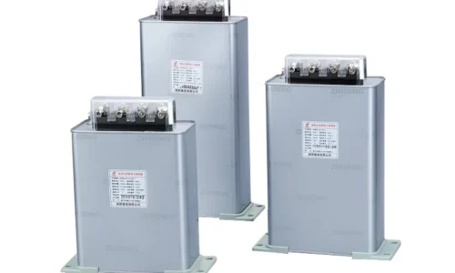
Understanding the Role of a Capacitor Bank in Power Systems
When electrical systems run with poor power factor, inefficiencies pile up quickly. Motors strain harder, cables heat up more than they should, and utility bills climb month after month. This is where a capacitor bank comes into play—compensating for reactive power and bringing the system back into balance.
But here’s the thing. Simply installing any capacitor bank won’t solve the problem. Size matters quite a bit. An undersized unit barely makes a dent in power factor improvement. Meanwhile, an oversized installation creates over-compensation issues that cause voltage fluctuations and equipment stress. Neither scenario ends well.
The selection process requires careful analysis of existing loads, target power factor goals, and system characteristics. It sounds complicated at first glance, but breaking it down step by step makes the whole thing manageable.
Why Proper Capacitor Bank Sizing Is Critical
The Cost of Getting It Wrong
Choosing the wrong size has real consequences—financially and operationally. Undersized banks fail to correct power factor adequately, meaning penalty charges from the utility continue showing up on monthly statements. Those fees add up surprisingly fast for facilities with significant inductive loads.
Oversized installations bring different problems. Leading power factor conditions stress transformers and can trip protective devices unexpectedly. Some utilities actually penalize customers for leading power factor too, which is something many facility managers don’t realize until they see the bill.
Benefits of Correct Sizing
When the capacitor bank matches system requirements properly, several advantages emerge:
- Reduced reactive power charges on utility bills
- Lower current flow through cables and equipment
- Extended lifespan for motors and transformers
- Improved voltage regulation throughout the facility
- Potential reduction in maximum demand charges
These benefits compound over time. A well-sized installation often pays for itself within one to three years, depending on electricity rates and usage patterns.
Key Factors Affecting Capacitor Bank Selection
Load Analysis and Power Consumption
Understanding what loads exist in the system is the foundation of proper sizing. Industrial facilities typically have motors, compressors, welding machines, and various other inductive equipment. Each contributes to reactive power demand differently.
Some important considerations include:
- Total connected load versus actual running load
- Operating hours for different equipment
- Seasonal variations in production or usage
- Plans for future expansion or equipment additions
Nameplate data provides a starting point, but actual measurements tell the real story. A power analyzer connected at the main distribution point captures true consumption patterns over days or weeks.
Target Power Factor Requirements
Utilities set minimum power factor requirements—usually somewhere between 0.90 and 0.95. Falling below triggers penalty charges. But aiming slightly higher than the minimum makes sense in most cases. Hitting exactly 0.95 when the target is 0.95 leaves no margin for load variations.
A target of 0.96 or 0.97 provides a comfortable buffer without excessive cost.
Step-by-Step Process for Calculating Capacitor Bank Size
The calculation itself follows a fairly straightforward formula, though gathering accurate input data takes more effort than the math.
- Measure the existing power factor under normal operating conditions using a quality power analyzer
- Determine the active power consumption in kilowatts during typical operations
- Identify the desired target power factor based on utility requirements and operational goals
- Apply the sizing formula to calculate required reactive power compensation
- Add a margin of 10 to 20 percent for load growth and measurement variations
- Select a standard capacitor bank size that meets or slightly exceeds the calculated value
The fundamental formula for sizing works as follows:
Required kVAR = kW × (tan φ₁ – tan φ₂)
Here, φ₁ represents the angle corresponding to current power factor, and φ₂ corresponds to the target power factor. Trigonometric tables or online calculators make quick work of finding tangent values.
Capacitor Bank Sizing Reference Chart
Active Power (kW) | Current PF | Target PF | Estimated kVAR Required |
100 | 0.70 | 0.95 | 69 |
150 | 0.72 | 0.95 | 97 |
250 | 0.75 | 0.95 | 136 |
400 | 0.78 | 0.95 | 189 |
600 | 0.80 | 0.95 | 228 |
1000 | 0.82 | 0.95 | 347 |
1500 | 0.85 | 0.95 | 437 |
Facilities with widely varying loads should consider automatic capacitor bank systems with multiple switching steps. These adjust compensation dynamically as loads change throughout the day.
Fixed Versus Automatic Capacitor Bank Systems
When Fixed Banks Work Well
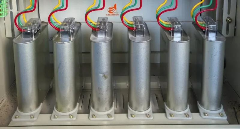
Fixed capacitor banks suit applications with consistent, predictable loads. A pump station running 24 hours with minimal variation, for instance, works perfectly fine with fixed compensation. Installation costs less, maintenance is simpler, and there are fewer components to fail.
When Automatic Systems Make More Sense
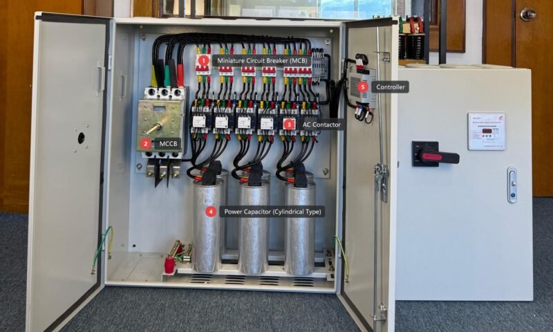
Automatic banks use controllers and contactors to switch capacitor stages in and out based on real-time power factor measurements. Manufacturing facilities with varying production schedules benefit significantly from this approach. The system prevents over-compensation during light load periods while providing full correction during peak production.
Components of a typical automatic system include:
- Power factor controller with adjustable settings
- Multiple capacitor stages sized appropriately
- Switching contactors rated for capacitive loads
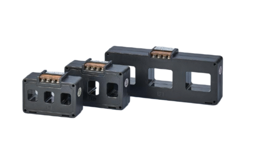
- Current transformers for measurement input
- Discharge resistors for safety
Common Pitfalls in Capacitor Bank Selection
Even experienced engineers sometimes overlook important factors. A few recurring mistakes show up repeatedly in field observations:
- Relying solely on nameplate ratings instead of actual measurements
- Ignoring harmonic content from variable frequency drives and other non-linear loads
- Forgetting that ambient temperature affects capacitor lifespan significantly
- Skipping detuning reactors in systems with notable harmonic distortion
- Choosing the cheapest option without considering long-term reliability
Harmonics deserve special attention. Systems with variable frequency drives, LED lighting, and other electronics generate harmonic currents that can resonate with capacitor banks. Detuned or filtered designs prevent problems in these environments. If you want to know more about capacitor bank selecting, please read How many types of capacitor banks are there.
FAQ
What is the lifespan of a typical capacitor bank?
Quality capacitor banks generally last 10 to 15 years under normal operating conditions. However, high ambient temperatures, harmonic distortion, and voltage variations shorten lifespan considerably. Regular inspection helps identify aging units before failure.
Can a capacitor bank be installed without professional help?
Technically possible for simple fixed installations, but generally not recommended. Electrical systems carry inherent risks, and improper installation can damage equipment or create safety hazards. Professional assessment ensures proper sizing, protection, and compliance with local codes.
How quickly does a capacitor bank pay for itself?
Payback periods typically range from 6 months to 3 years depending on electricity rates, penalty structures, and usage patterns. Facilities with high reactive power penalties see faster returns. An energy audit or utility bill analysis helps estimate potential savings before investment.