Someone once wired a current transformer backward. The meters showed negative values. The protection relays stayed quiet when they should have tripped.
This article walks through how to connect a Current Transformer in real-world installations. The practical steps, common mistakes, and details that matter.
Table of Contents
What a Current Transformer Does Before Connection
Before connecting a current transformer, it helps to remember what it actually does.
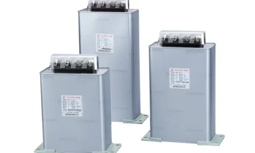
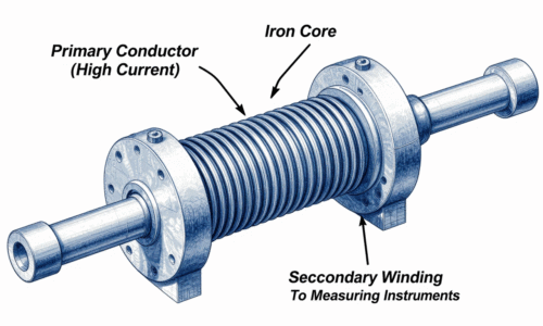
The device reduces high primary current to a lower, measurable secondary value. Standard secondary currents are 1A and 5A. This allows meters and relays to work safely without handling high current directly.
The primary side is usually a busbar or cable passing through the device’s opening. No direct electrical connection is needed on the primary for most low voltage versions. For high voltage units, the primary is often a single turn built into the insulation.
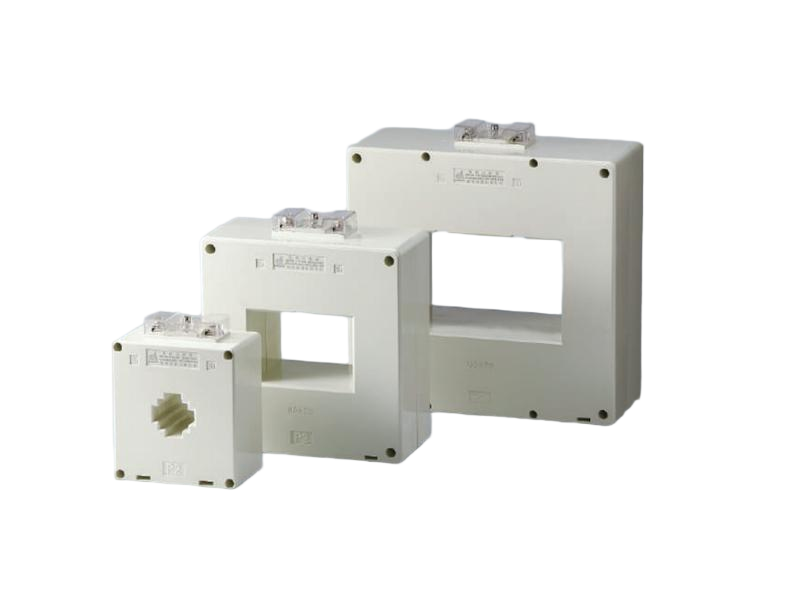
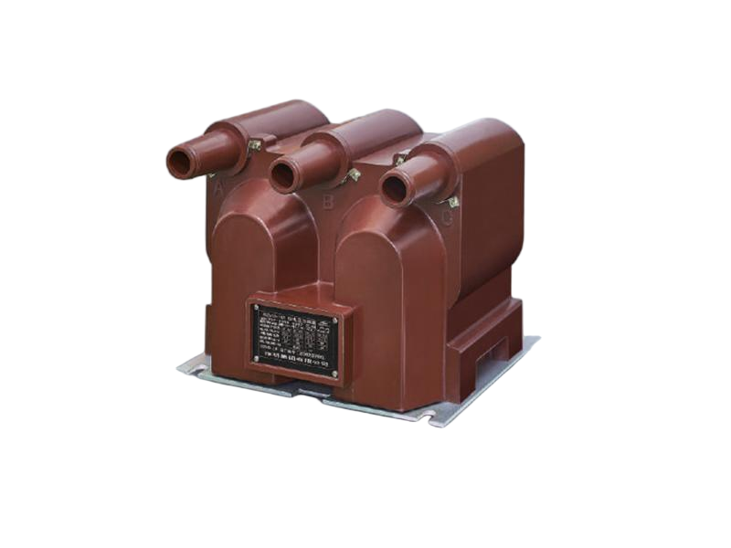
Different types are used for different jobs. A High Voltage Current Transformer sits in substations. A Low Voltage Current Transformermounts inside panels. A Zero Sequence Current Transformer surrounds all three phases to detect ground faults. Each connects slightly differently, but the core principles are the same.
Step-by-Step Guide to Connect a Current Transformer
Mount the Current Transformer
For a Low Voltage Current Transformer, the device is usually clamped around the primary conductor or busbar. The conductor must pass through the center opening. Nothing else should be inside that opening except the intended conductor.
For a high voltage version, the current transformer is often mounted on a steel structure or inside a switchgear compartment. The primary conductor is bolted to its terminals.
Zero sequence current transformer installation is different. All three phase conductors must pass through the same opening. The neutral conductor may also be included depending on the grounding scheme.
Connect the Primary Side of a Current Transformer
Primary connection depends on the current transformer type.
For a High Voltage Current Transformer, the primary is connected in series with the line. The device has dedicated primary terminals. The line current flows through the primary winding.
For a low voltage version, the primary conductor is simply passed through the window. No electrical connection is made to the current transformer itself. The number of primary turns affects the ratio. One pass through the opening equals one primary turn. Some devices allow multiple passes to change the ratio.
Safety warning: Never open the secondary circuit of a current transformer under load. An open secondary can induce dangerously high voltage.
Wire the Secondary Side of a Current Transformer
Secondary wiring is where most mistakes happen.
The secondary terminals of a current transformer are usually marked S1 and S2. These connect to the meter or relay.
One common mistake is swapping S1 and S2. This reverses polarity. The meter reads negative or the relay operates incorrectly. Polarity matters especially for directional protection or differential schemes involving a current transformer.
The secondary wires should be sized appropriately. Long runs need larger wire to keep the burden low. The secondary circuit must be continuous. No open circuits.
Ground the Secondary Circuit of a Current Transformer
One secondary terminal of the current transformer should be grounded. The ground connection prevents the secondary voltage from rising to dangerous levels if insulation fails.
The grounding point is typically at the current transformer itself or inside the panel where its secondary terminates. Only one ground per circuit to avoid ground loops.
Verify Polarity and Ratio of a Current Transformer
After physical connection comes verification.
Polarity can be verified by applying a small Direct Current voltage to the primary and observing the secondary reading. If the reading is positive when expected, polarity is correct. Primary injection testing using a test set is another reliable method.
The ratio test confirms that the turns ratio matches the nameplate rating. This step catches wiring errors before the system goes live.
For a zero sequence current transformer, the verification is slightly different. With all three phases balanced, the secondary output should be near zero. Any significant output indicates a wiring problem or a ground fault.
Wiring Configurations for a Current Transformer
The table below shows common connection schemes for different applications.
| Application | Connection Method | Polarity Requirement |
|---|---|---|
| Single-phase metering | Secondary to meter | S1 to meter line, S2 to meter load |
| Three-phase metering | Three units, one per phase | Consistent orientation |
| Overcurrent protection | Secondary to relay | S1 to relay input |
| Directional protection | Secondary to relay | Must match reference voltage |
| Ground fault detection | Zero sequence type | All phases through one unit |
Common Mistakes When Connecting a Current Transformer
Open Circuit on Secondary Side
The most dangerous mistake. A current transformer with an open secondary can generate dangerously high voltage. Always short the secondary before disconnecting any wiring.
Wrong Polarity
Swapping S1 and S2 on a current transformer causes reversed polarity. The meter reads backward. Protection relays may operate when they should not.
Multiple Grounds
Grounding both secondary terminals of a current transformer creates a ground loop. This can cause circulating currents and measurement errors. Only one ground per circuit.

Wrong Ratio
Using a current transformer with the wrong ratio produces inaccurate readings. Always match the ratio to the primary current.
Incorrect Primary Turns
Some current transformers allow multiple primary passes. One pass through the window equals one turn. Two passes equal two turns. This changes the effective ratio.
Practical Examples of Connecting a Current Transformer
Low Voltage Current Transformer for Metering
A facility needs to measure current on a low voltage feeder. The electrician selects a low voltage current transformer. The primary conductor passes through the window once. The secondary wires run to a power meter, S1 to S1, S2 to S2.
High Voltage Current Transformer for Protection
A substation feeder uses a high voltage current transformer for overcurrent protection. The primary is connected in series with the line. The secondary connects to a protection relay.
Zero Sequence Current Transformer for Ground Fault Detection
A commercial building uses a Zero Sequence Current Transformer for ground fault protection. All three phase conductors pass through the device’s opening. Under normal conditions, the secondary current is near zero.
Safety Practices When Working with a Current Transformer
- De-energize the primary circuit before working on a current transformer if possible
- Apply appropriate Personal Protective Equipment (PPE)
- Never open secondary terminals of a current transformer
- Always short the secondary terminals before removing the device
- Ground the secondary circuit of the current transformer
- Replace all covers before turning on power
Conclusion on Connecting a Current Transformer
Connecting a current transformer requires attention to detail. Mount it correctly. Wire the secondary with correct polarity. Ground one point. Verify before energizing.
If you want to know more about Current Transformer, please read How to check if current transformer is working or not.
FAQ
What happens if the secondary terminals of a current transformer are left open while the primary is energized?
The secondary voltage can rise to dangerously high levels. This applies to all types of current transformers. Always short the secondary before disconnecting any wiring.
How can you tell if a current transformer is wired with the correct polarity after installation?
Apply a small Direct Current voltage to the primary and observe the secondary reading. If positive when expected, polarity is correct. If negative, the wires are swapped.
Why is grounding required on the secondary circuit of a current transformer?
Grounding one secondary terminal prevents dangerous voltage rise if insulation fails. Only one ground per circuit. This is a standard safety requirement for all current transformer installations.