Electrical power systems face constant challenges with reactive power management. Motors, transformers, and other inductive equipment demand reactive current that burdens the grid without performing useful work. The solution most commonly deployed? A shunt capacitor bank.
The term “shunt” simply refers to how the capacitors connect — in parallel with the load or system, rather than in series with it. This parallel connection defines both how the equipment operates and what benefits it provides. Though the concept seems basic, shunt capacitor banks perform critical functions across utility and industrial applications worldwide.

Table of Contents
How a Shunt Capacitor Bank Works
The Basic Operating Principle
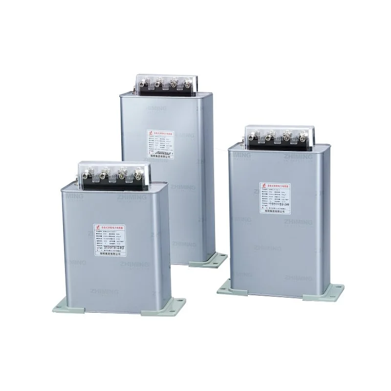
A shunt capacitor bank connects across the power line, creating a parallel path that draws leading current from the source. This leading current offsets the lagging current that inductive loads require. The net effect reduces total reactive current flowing from the supply.
Why does this matter? Reactive current occupies transmission capacity without delivering useful power. It increases losses in cables, transformers, and generators. By providing reactive power locally through a shunt capacitor bank, systems operate more efficiently. Less current flows through upstream equipment for the same real power delivery.
The physics are straightforward enough. Capacitors store and release energy in alternating fashion, 90 degrees out of phase with voltage. Inductors do the same, but with opposite phase relationship. Combining both creates partial or complete cancellation of reactive current.
Voltage Support Function
Beyond power factor correction, a shunt capacitor bank provides voltage support — sometimes as its primary purpose. Voltage tends to sag under heavy load conditions due to reactive power demand. Capacitors counteract this sag by injecting reactive power into the system.
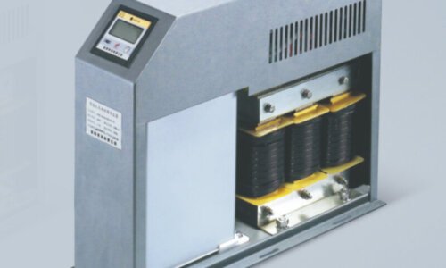
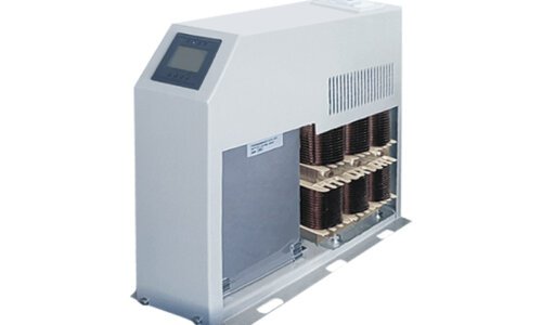
While utilities install large capacitor banks at strategic points in distribution networks for voltage regulation, the same principle applies at the facility level. A low voltage power capacitor bank can be deployed within a factory or building’s electrical infrastructure to maintain acceptable voltage levels during peak demand periods, preventing drops below operational limits. This creates the effect of having a local reactive power source, reducing dependency on drawing it from the upstream grid and improving overall voltage stability close to the load.
Shunt Capacitor Bank Applications and Benefits
Common Installation Locations
Shunt capacitor banks appear throughout electrical infrastructure at various voltage levels:
- Utility substations for transmission and distribution support
- Industrial plant main switchboards for facility-wide correction
- Individual motor terminals for targeted compensation
- Pole-mounted units on distribution feeders
- Large commercial building electrical rooms
Location affects sizing, protection requirements, and operational strategy. A utility substation bank might contain thousands of kVAr across multiple switching stages. A motor terminal installation might be a single small unit.
Key Benefits Summarized
Benefit Category | Specific Improvement | Typical Impact |
Power factor | Correction from lagging to near unity | 15-30% reduction in reactive demand |
Voltage regulation | Support during heavy loading | 2-5% voltage improvement |
System losses | Reduced current flow | 5-15% loss reduction |
Equipment capacity | Released transmission capability | Increased real power transfer |
Utility charges | Avoided power factor penalties | Significant cost savings |
Protection Requirements
Shunt capacitor banks need protection systems matching their operating characteristics:
- Overcurrent protection for fault conditions
- Overvoltage protection against excessive voltage stress
- Unbalance detection for internal element failures
- Undervoltage lockout preventing inappropriate energization
- Inrush management for switching transients
FAQ
Where are shunt capacitor banks typically installed?
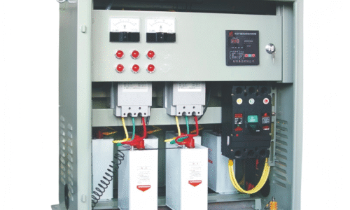
Installation locations span the entire power system hierarchy. Utilities install large shunt capacitor banks at transmission substations and distribution substations for system-wide voltage support and reactive power management. Within industrial facilities, installations commonly occur at the main service entrance for overall power factor correction, though distributed installation at motor control centers or individual loads provides additional benefits. Commercial buildings often locate shunt capacitor banks in main electrical rooms alongside switchgear.
How many suppliers should I compare before deciding?
Proper sizing requires understanding actual reactive power demand across operating conditions. Simply calculating connected motor horsepower and applying a generic correction factor produces only rough estimates. More accurate sizing involves power system analysis measuring real and reactive power under various load conditions, then determining what compensation brings power factor to target levels without overcorrection during light load periods. Oversized shunt capacitor banks push power factor into leading territory, potentially causing overvoltage and incurring penalties from some utilities.
What causes shunt capacitor bank failures?
Several factors contribute to premature failure. Overvoltage stress — whether from steady-state conditions or transient events — degrades dielectric insulation progressively until breakdown occurs. Harmonic currents from nonlinear loads increase heating beyond design limits and can excite damaging resonance conditions. Frequent switching operations wear contactors and stress capacitor elements through repeated inrush current exposure.