Table of Contents
The Fundamental Reason for Using a Current Transformer in High-Voltage Zones
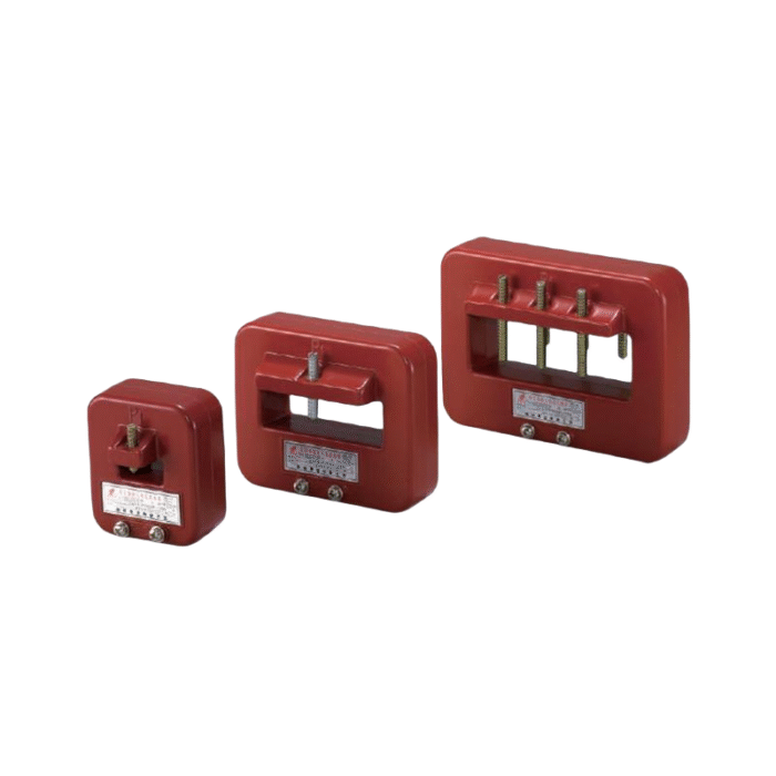
Walking into a substation, one notices the sheer scale of the infrastructure. Massive circuit breakers, towering busbars, and rows of control cabinets. Amidst all this heavy hardware, the current transformer often appears as a relatively modest component—sometimes just a donut-shaped ring clamped around a thick conductor. But its role is anything but minor.
The simple truth is, you cannot directly connect standard measuring instruments to high-voltage lines. It’s not just impractical; it’s dangerous. Substations deal with currents that can range from a few hundred to several thousand amperes. Trying to run those currents directly into a meter panel would require enormous, expensive wiring and would expose operators to lethal voltages. So the current transformer sits at that critical junction, acting as a bridge between the raw power of the grid and the delicate safety of the control room.
Isolation as the Primary Motivation
Breaking the Galvanic Connection
One of the less obvious but most critical functions is electrical isolation. When a current transformer is installed, there is no direct metallic path between the primary conductor (carrying high voltage) and the secondary circuit (connected to meters and relays). The connection is purely magnetic.
This separation is a huge deal. It means that even if a piece of metering equipment fails or a technician accidentally touches a terminal in the relay panel, they are only exposed to the secondary circuit’s low voltage (typically under 600V, often much lower). The lethal 11kV, 33kV, or even 220kV remains on the other side, completely isolated. It’s a safety buffer that allows personnel to work on monitoring equipment without requiring the substation to be de-energized. That kind of operational flexibility—being able to swap out a meter while the line is live—is something that gets taken for granted until one considers the alternative.
Standardization: Why the 5-Amp Secondary Became the Norm
Interchangeability and Practicality
Another reason the current transformer is so universally adopted comes down to standardization. In most substations, regardless of whether the primary current is 100A or 4000A, the secondary output is standardized to either 5A or 1A.
From an observational standpoint, this standardization simplifies everything downstream. Engineers don’t have to custom-design protection relays for every unique line. A relay rated for 5A input can be used anywhere in the facility. Wiring sizes remain manageable—imagine trying to run 4000A copper cables from the yard into the control building. It wouldn’t just be expensive; it would be physically impossible. The current transformer scales that massive primary current down to a level that ordinary wires can handle. It’s a bit like using a map instead of trying to carry the entire landscape around.
A Look at the Alternatives
There are other ways to sense current, such as Hall effect sensors or Rogowski coils. But in a high-reliability environment like a substation, the traditional current transformer has staying power. The table below highlights why it remains the dominant choice.
| Feature | Conventional Current Transformer | Electronic Sensors (Hall Effect, etc.) |
|---|---|---|
| Power Source | Self-powered (derived from the line) | Requires external DC supply |
| Reliability | Passive, no electronics to fail | Active components susceptible to surges |
| Isolation | Inherent magnetic isolation | Often requires additional isolation circuitry |
| Linearity Under Fault | Predictable saturation behavior | Can be damaged by high fault currents |
There’s a certain comfort in the passive nature of the current transformer. No power supply means no single point of failure that can knock out the monitoring system. In a substation, where reliability is paramount, that simplicity matters a great deal.
Reliability Under Extreme Conditions
Handling Fault Currents
Substations are not gentle environments. Faults happen. When a short circuit occurs, the current can spike to 20 or even 40 times the normal load in a fraction of a second.
One might assume that such a massive surge would destroy a current transformer, but that’s where the engineering gets interesting. Protection-class CTs are specifically designed to withstand these extreme events without damage. They’re built with robust cores and ample insulation to handle the electromagnetic forces and thermal stress. When a fault occurs, the CT continues to provide a faithful (though scaled-down) representation of the fault current to the protection relays. Those relays then trigger the circuit breakers to clear the fault. Without the CT, the relay would be blind. It’s one of those cases where a component is expected to perform perfectly under the worst possible conditions. If you want to know more about current transformer, please read What is the current transformer.
FAQ
Why can’t a substation just use a voltage transformer to measure current?
A voltage transformer measures potential difference, not the flow of electrons. To derive current from voltage, one would need to know the impedance of the line, which is rarely constant. A current transformer directly measures the magnetic field generated by the current, providing a true reading regardless of line conditions. They serve different purposes and aren’t interchangeable.
What happens if a current transformer fails in a substation?
Failure is rare, but when it occurs, the consequences depend on the type. If the secondary circuit opens while energized, dangerous overvoltages can occur, potentially damaging insulation and creating arc flash hazards. If the core fails, the protection relay may lose signal, requiring the line to be taken out of service for replacement. This is why CT circuits are treated with the same caution as high-voltage equipment.
Is there a trend toward replacing traditional CTs with digital sensors?
There is a growing presence of optical and low-power wireless sensors in newer, compact substations, particularly for gas-insulated switchgear. However, for conventional air-insulated substations and critical protection applications, the traditional current transformer remains deeply entrenched. The transition is slow, largely because the existing infrastructure, relay systems, and technician training are built around the 5A secondary standard.