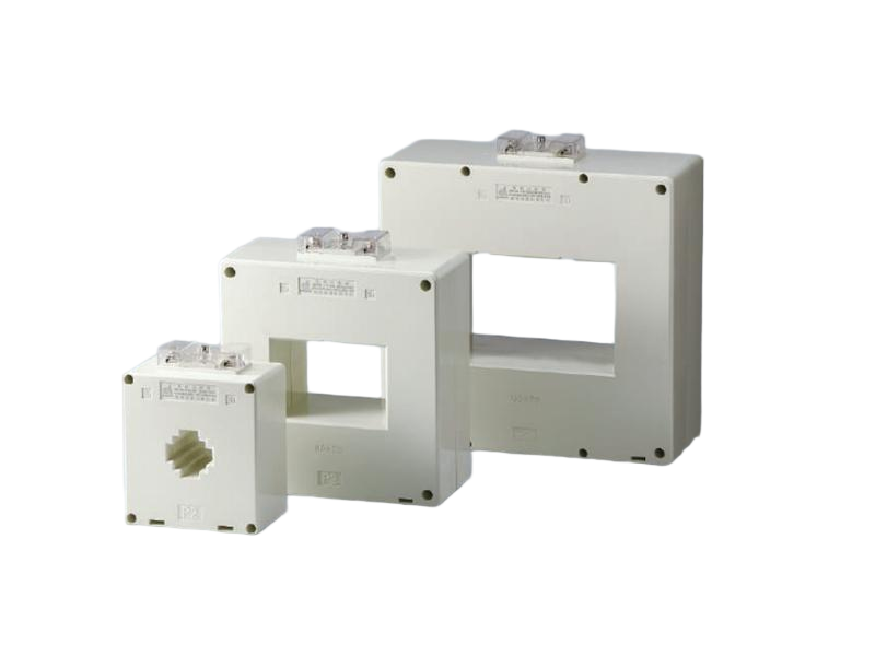
If you’ve ever opened up an electrical panel, you’ve probably noticed those little donut-shaped rings clamped around the wires. That right there is the Current Transformer, or CT. It’s one of those devices that looks incredibly simple—just a coil of wire around a core—but it plays a massive role in keeping high-voltage systems safe and measurable.
It’s easy to assume that measuring electricity is straightforward, but when you’re dealing with hundreds or thousands of amps, you can’t just run the main line directly into a meter. That would be dangerous, and frankly, it just wouldn’t work. The Current Transformer solves this by creating a scaled-down replica of the current flowing in the main conductor. It lets instruments do their job without being exposed to the lethal voltages present in the primary circuit.
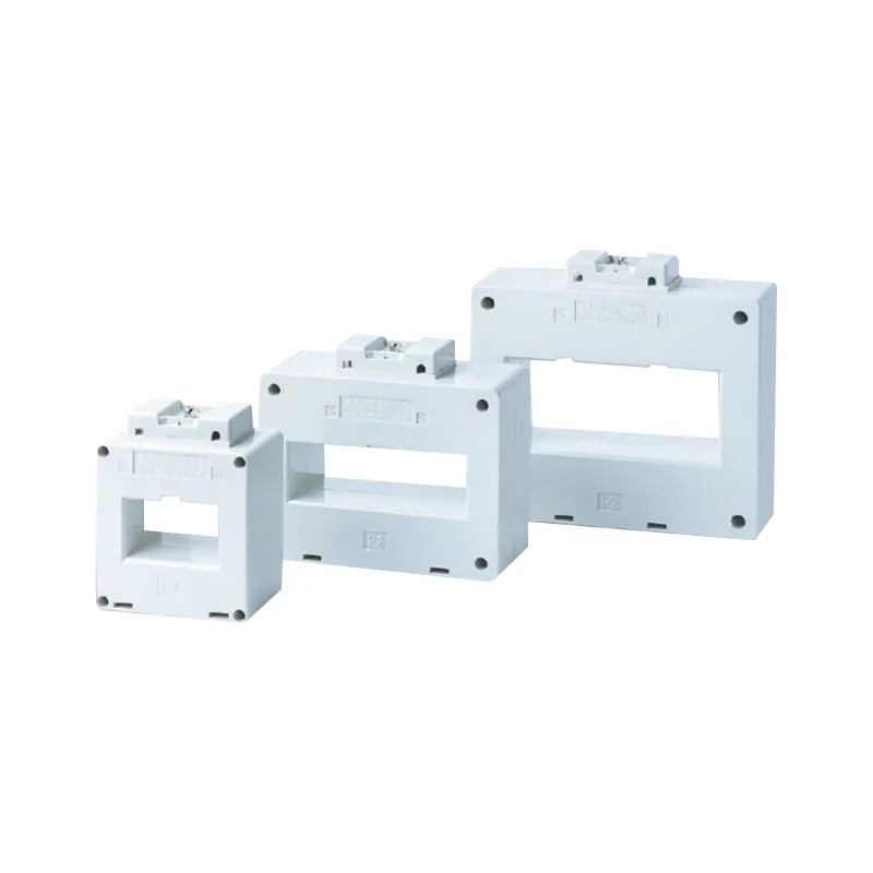
Table of Contents
How a Current Transformer Actually Works
You might recall something about electromagnetic induction from physics class. The principle here is the same, but the application is specific—especially when looking at a low voltage current transformer, where the design prioritizes easy installation and space efficiency. Essentially, the Current Transformer acts as a step-down transformer. The primary winding is often just the single busbar or cable passing through the center (that counts as one turn), while the secondary winding is many turns of wire wrapped around a ferromagnetic core.
When current flows through that main conductor, it generates a magnetic field. That field induces a proportional current in the secondary winding. If the ratio is 1000:5, for example, when 1000 amps flow on the primary side, exactly 5 amps flow out of the secondary leads to the meter. It’s a clean, isolated way to get the data needed.
Selection Pitfalls and Safety Quirks
One thing that surprises a lot of people new to electrical work is the danger of an “open circuit” on the secondary side. With a standard voltage transformer, if you leave the secondary leads unconnected, nothing really happens. But with a Current Transformer, you never, ever want to open the secondary circuit while the primary is energized.
It’s one of those rules that gets repeated constantly because the consequences are immediate. If the secondary circuit is open, the magnetic flux has nowhere to go. It skyrockets, generating extremely high voltage spikes—enough to destroy the insulation and create a serious arc flash hazard. So, before disconnecting a meter, the secondary leads always get shorted out first. It’s just a non-negotiable safety step.
Key Selection Factors for Current Transformers
Choosing the right unit involves more than just matching the wire size. There are a few parameters that need to be spot on to ensure the readings make sense.
Burden Rating: This refers to the load the CT can drive. It’s measured in VA (Volt-Amps). If the connected meters, relays, and wires demand more VA than the CT can supply, accuracy drops significantly.
Accuracy Class: For metering, you typically see classes like 0.5 or 1.0 (meaning 0.5% or 1.0% accuracy). For protection relays, you’ll see classes like 5P10 or 10P20, which indicate the accuracy during fault conditions—a very different scenario.
Ratio: This is the number on the nameplate. It’s essential to pick a ratio where the normal operating current falls between 50% and 100% of the primary rating. Running a 2000:5 CT on a 200-amp line might technically work, but the readings will be at the very bottom of the accuracy curve.
FAQ
Can a Current Transformer be used for both metering and protection simultaneously?
It is generally not recommended to use the same core for both functions. Metering CTs are designed for accuracy within the normal operating range but saturate quickly during faults to protect the meter.
Why is the secondary of a Current Transformer usually rated at 5 amps or 1 amp?
Historically, 5 amps became the standard in North America (ANSI/IEEE) because it provided a good balance between signal strength and manageable wire sizes. In many international markets (IEC), 1 amp is more common, which allows for longer cable runs with less voltage drop. It depends entirely on the regional standards and the specifications of the metering equipment.
What happens if a Current Transformer is installed backwards?
If the CT is installed with the polarity reversed (facing the wrong direction on the cable), the current reading itself will still show magnitude, but the phase angle will be 180 degrees off. For simple ammeters, this doesn’t matter.