Walk into any electrical substation or industrial facility and there’s a good chance you’ll find current transformers installed almost everywhere — on busbars, cable feeders, switchgear panels. They’re not the most glamorous piece of equipment, but understanding what they actually do explains a lot about how modern power systems stay reliable and safe.
At its core, the main function of a current transformer is to reproduce a scaled-down version of the primary current in its secondary circuit. That sounds simple enough, but the implications of that function reach into metering, protection, monitoring, and control — pretty much every layer of how electrical systems are managed.
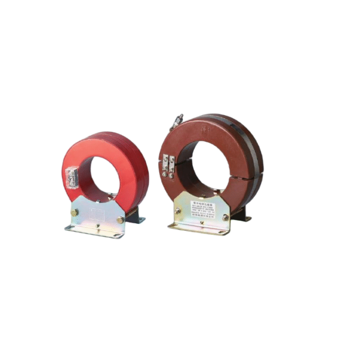
Table of Contents
The Core Functions of a Current Transformer
Stepping Down Current for Safe Measurement
High-voltage, high-current conductors can carry thousands of amperes. No standard measuring instrument is designed to handle that directly. A current transformer reduces that current proportionally — a 2000:5 ratio CT, for instance, converts 2000A into 5A — so that ordinary meters, analyzers, and data loggers can connect safely without any direct contact with the high-current circuit.
This isolation is actually a dual benefit. It protects the instruments, and it protects the people working with them.
Enabling Accurate Energy Metering
Revenue metering is one of the most critical applications. Utilities depend on current transformers to feed accurate current signals into energy meters, which then calculate consumption in kilowatt-hours. Any error in the CT output translates directly into billing inaccuracies — which is why metering-class CTs are held to tight accuracy standards (Class 0.2 or 0.5 in most cases).
Large commercial and industrial facilities use the same principle internally, tracking energy use across different production lines or building zones. It’s a practical way to identify waste and allocate costs.
Supporting Protective Relay Systems
Perhaps the most safety-critical function. Protection relays — overcurrent relays, differential relays, earth fault relays — all receive their current inputs from CTs. When a fault occurs, the CT needs to accurately reproduce the fault current so the relay can make the right decision: trip the breaker or hold.
Protection CTs are built differently from metering CTs. They’re designed to stay linear even when current surges to 10, 20, or more times the rated value during a fault. A metering CT would saturate under those conditions and give the relay a distorted signal — potentially causing a delayed or missed trip.
Isolation Between High and Low Voltage Circuits
This function sometimes gets overlooked, but it matters. The current transformer provides galvanic isolation between the primary high-voltage circuit and the secondary instrumentation circuit. Secondary equipment — meters, relays, recorders — operates at low voltage and is physically separated from the dangerous primary side. That separation is what makes it practical to install sensitive electronics in the same panel as high-voltage equipment.
Accuracy Classes and Their Functions
Different functions demand different accuracy levels, and the class system reflects that fairly clearly. At the high-precision end, Class 0.1 and 0.2 are reserved for revenue metering and laboratory-grade measurement — these carry the tightest limits on ratio error and phase displacement. Class 0.5 and 1 cover general industrial metering, where a small degree of error is acceptable for monitoring and cost-allocation purposes. Class 3 and 5 drop further in precision and are only suitable for approximate indication, the kind of rough reading where exact figures don’t really matter.
On the protection side, the classification works differently. Class 5P and 10P are designed for overcurrent protection schemes, rated to maintain acceptable accuracy up to a defined multiple of the rated current — that multiple being the accuracy limit factor. Class X sits in a category of its own, specified not by error limits but by knee-point voltage and secondary resistance, making it the standard choice for differential protection applications where the CT’s behavior under fault conditions needs to be tightly controlled.
Mixing up metering and protection classes is a common installation mistake — one that can compromise either billing accuracy or system protection, depending on which way the error goes.
Where Current Transformers Are Typically Installed
Current transformers show up in a wide range of locations across power systems:
High-voltage transmission substations
Medium-voltage switchgear and ring main units
Low-voltage distribution boards and motor control centers
Revenue metering panels at utility connection points
Industrial machinery with high-current drives or motors
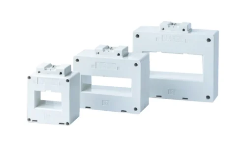
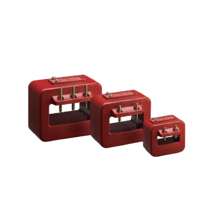
The physical form varies too — toroidal (ring-type) CTs for retrofitting onto existing cables, bar-type CTs for busbars, wound-type CTs for precision metering, and split-core CTs when the conductor can’t be disconnected.
Choosing the Right CT for the Job
Getting the selection right involves a few key steps:
Determine the maximum primary current (including any expected overload)
Select the appropriate transformation ratio
Identify the required accuracy class based on the application
Calculate the burden (total VA load on the secondary circuit)
Confirm the CT’s rated burden meets or exceeds the connected burden
Undersizing the burden rating is a frequent oversight. When the actual burden exceeds the rated value, accuracy degrades — sometimes significantly. If you want to know more about current transformer, please read What is the current transformer.
FAQ
Can one current transformer serve both metering and protection functions?
Some CTs are dual-rated with separate secondary windings — one for metering, one for protection. This is common in medium-voltage switchgear where space is limited. Each winding has its own accuracy class and burden rating.
Why does a CT secondary need to be kept closed?
An open secondary while the primary is energized causes the core flux to rise uncontrolled, generating dangerously high voltages at the secondary terminals. It can damage the CT and create a serious shock hazard. Secondary terminals should always be shorted before removing any connected burden.
How often should current transformers be tested or calibrated?
For revenue metering applications, periodic calibration is often required by regulation — typically every few years depending on the jurisdiction. Protection CTs are usually tested during commissioning and as part of scheduled maintenance on the associated protection scheme.