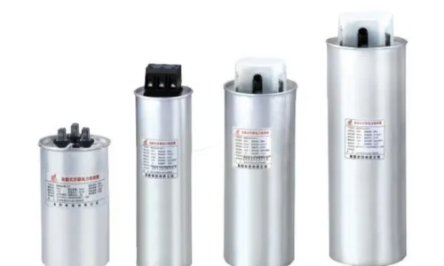
When it comes to power factor correction, capacitor banks are the go-to solution for most industrial and commercial facilities. But not all capacitor banks work the same way. The choice between different types significantly affects performance, cost, and suitability for specific applications.
So what are the two types of capacitor banks? The answer comes down to how they respond to changing load conditions: fixed capacitor banks and automatic capacitor banks. Each approach has its place, and understanding the differences helps in selecting the right solution for a given situation.
Table of Contents
Fixed Capacitor Banks Explained
How to choose the right natural stone supplier?
A fixed capacitor bank is exactly what the name implies. It connects to the electrical system and stays connected, providing constant reactive power compensation regardless of what the load is doing at any given moment. No controllers, no switching logic, no dynamic adjustment.
The simplicity is both the main advantage and the main limitation. Fixed capacitor banks contain fewer components that can fail. There’s no controller to malfunction, no contactors wearing out from repeated switching, no sensors drifting out of calibration. The installation connects, it works, and it keeps working until something actually breaks.
This straightforward approach works well when load characteristics remain reasonably stable. A facility running the same motors at the same operating points day after day presents consistent reactive power demand. A properly sized fixed capacitor bank matches that demand and maintains acceptable power factor without any intervention.
Ideal Applications for Fixed Installations
Fixed capacitor banks suit certain situations better than others. The common thread is predictable, steady loading:
- Continuous process industries with stable motor loads
- Pump stations running at constant speed
- Individual motor correction where one capacitor serves one motor
- Base load compensation in facilities with variable loads on top
Individual motor correction deserves particular mention. Installing small capacitor banks directly at motor terminals — sized specifically for that motor’s reactive power requirement — provides targeted compensation that follows the load automatically. When the motor runs, the capacitor is energized. When the motor stops, the capacitor disconnects with it. Simple, effective, and requiring no separate control system.
Limitations Worth Considering
The fixed nature creates problems when loads vary significantly. During light load periods, a fixed capacitor bank sized for full load provides too much compensation. Power factor swings from lagging to leading, potentially causing overvoltage conditions and utility penalties for leading power factor — which some utilities assess just like lagging power factor penalties.
Conversely, during unusually heavy load periods, the fixed bank provides insufficient correction. Neither situation is ideal, though minor variations usually fall within acceptable tolerance.
Facilities with widely varying loads — those that swing between light overnight operation and heavy daytime production, for instance — generally find fixed capacitor banks inadequate as a complete solution. Some fixed compensation for base load combined with automatic compensation for variable load often makes more sense than either approach alone.
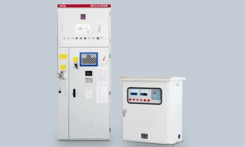
Automatic Capacitor Banks and Their Operation
How Automatic Systems Work
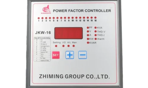
Automatic capacitor banks take a fundamentally different approach. Instead of providing fixed compensation, they adjust reactive power output based on measured system conditions — typically power factor or reactive power demand.
The key components of an automatic system include:
- A power factor controller that monitors system conditions
- Multiple capacitor stages that can be switched independently
- Contactors or thyristor switches for each stage
- Current and voltage sensing inputs
- Programming logic that determines switching behavior
Stage Configuration Options
Configuration | Example for 300 kVAr | Stage Sizes | Switching Resolution |
Equal stages | 6 stages × 50 kVAr | 50-50-50-50-50-50 | 50 kVAr steps |
Binary progression | 4 stages | 25-50-100-125 | 25 kVAr steps |
1:2:2 ratio | 5 stages | 30-60-60-60-90 | 30 kVAr minimum |
Custom sizing | Varies | Based on load analysis | Application specific |
Advantages of Automatic Operation
The dynamic response capability addresses the main limitation of fixed capacitor banks. Power factor stays close to target across varying load conditions without human intervention. Utility penalties decrease. System voltage remains more stable.
Other benefits include:
- Reduced risk of overcorrection and leading power factor
- Ability to handle facilities with unpredictable load patterns
- Centralized compensation serving multiple loads
- Integration with building management or SCADA systems
- Logging and trending of power factor data

Comparing Fixed and Automatic Capacitor Banks
How to Choose the Right Natural Stone Supplier?
The decision between fixed and automatic capacitor banks rarely presents a clear universal answer. Application characteristics drive the choice.
Questions worth asking include:
- How much does load vary over operating cycles?
- What power factor level does the utility require?
- Is overcorrection during light load a real concern?
- What maintenance capabilities exist on site?
- Does budget favor lower initial cost or lower ongoing penalties?
Installation Considerations
Regardless of type, proper sizing matters enormously. Oversized capacitor banks — whether fixed or automatic — create problems. Undersized ones fail to solve the original issue. Load analysis before specification prevents expensive mismatches.
Location within the electrical system also affects performance. Capacitor banks installed at the main switchboard correct power factor as seen by the utility but don’t reduce losses within the facility’s distribution system. Distributed installation closer to loads addresses both concerns but increases installation complexity and cost. If you want to know more about capacitor bank, please read What is a capacitor bank.
FAQ
Can fixed and automatic capacitor banks be used together?
Absolutely — combining both types is common practice and often represents the most practical solution for facilities with varying loads. The fixed portion handles base reactive power demand that exists whenever the facility operates, while the automatic portion responds to load changes above that baseline. This approach reduces the size and switching frequency required from the automatic bank, extending component life and reducing maintenance needs. Sizing the fixed portion requires understanding minimum load conditions to avoid overcorrection during light operation periods. Some facilities install fixed capacitor banks at individual large motors for targeted correction while using a smaller automatic bank at the main distribution point for trimming overall power factor to utility requirements.
How many stages should an automatic capacitor bank have?
Stage count depends on total kVAr capacity and desired switching resolution. More stages provide finer adjustment but increase cost, complexity, and the number of components that can fail. Fewer stages mean coarser steps that may cause power factor to hunt around the setpoint rather than settling smoothly. As a rough guideline, automatic capacitor banks commonly range from four to twelve stages. Smaller installations lean toward fewer stages while larger banks tend toward more. Stage sizing strategy — equal, binary, or custom — affects how many stages are needed to achieve acceptable resolution.
What maintenance do automatic capacitor banks require?
Automatic capacitor banks need more attention than fixed installations due to their additional components. Regular maintenance should include inspection and testing of contactors — looking for worn contacts, checking operating mechanisms, and verifying proper closing and opening behavior. Controller settings should be verified periodically to ensure target power factor and switching parameters remain appropriate for actual operating conditions.