In real electrical systems, failures are not always dramatic. A current transformer can keep working while slowly losing accuracy. That kind of drift is hard to notice at first.
At the beginning, readings may still look fine. No alarms go off. But over time, small issues appear. Numbers may fluctuate. Different meters may show values that do not match. That is when people start wondering: is the current transformer still working properly?
A current transformer is supposed to provide stable, reliable current signals. But factors like temperature, load changes, and installation conditions can affect its performance over time. That is why regular checking matters.
This article covers practical ways to check a current transformer. The methods described here are based on common electrical testing practices. They do not require special equipment in most cases.
Table of Contents
What a Current Transformer Does
Before learning how to check a current transformer, it helps to understand what it actually does.
A current transformer converts high primary current into a lower secondary current that can be safely measured. The secondary current is typically 5A or 1A at full load. This allows meters and relays to work with lower, safer current levels.
The actual performance of a current transformer depends on several factors. These include winding condition, core stability, and the connected burden. If any of these is off, the output may not be accurate.
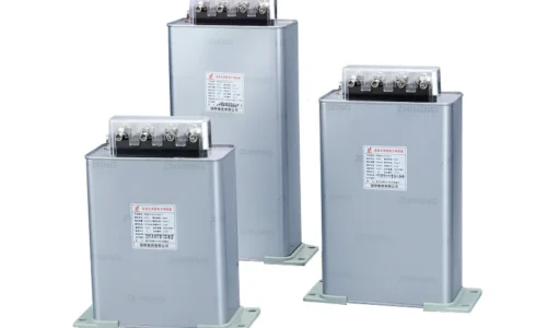
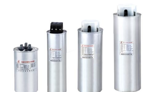
Different types of current transformers are used in different environments. Each type has its own application, but the basic checking methods are similar.
Signs That a Current Transformer Needs Checking
In practice, people usually start testing when something feels off. The issue may not be obvious at first, but there are small signals.
Common signs include:
- Meter readings that seem stable but not consistent with expected values
- Unexpected protection relay trips
- Slight temperature rise near the transformer enclosure
- Current fluctuations even when the load is steady
- Small differences between readings from two different meters
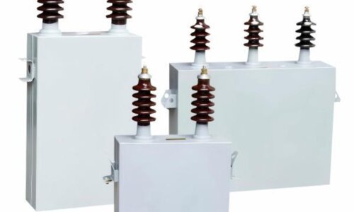
For example, a High Voltage Current Transformer in a substation may show different signs than a Low Voltage Current Transformer in a panel, but the basic checking approach remains the same.
None of these signs alone confirms a fault. But when several appear together, it is a good reason to check the current transformer more carefully.
In many real situations, these signs develop slowly. That makes early detection harder but more important. Regular checks help catch problems before they cause system issues.

Tools for Checking a Current Transformer
The tools needed for checking a current transformer are usually quite simple. Most electrical technicians already have them.
Typical tools include:
- Multimeter (for resistance and continuity checks)
- Clamp meter (for measuring secondary current)
- Insulation resistance tester (also called a megohmmeter)
These three tools are enough for most basic checks. In some cases, a portable current source may be needed for ratio tests. But that is less common for routine checks.
The key is not the tool itself. It is knowing what to look for and how to interpret the readings. A current transformer can pass a basic resistance test but still have accuracy issues under load.
Methods to Check a Current Transformer
There are several ways to check a current transformer. The method you choose depends on what tools you have and what kind of access you have to the installation.
Visual Inspection
The first step is always visual. Look at the current transformer carefully.
Check for:
- Cracks or physical damage on the housing
- Burn marks or discoloration
- Loose or corroded terminals
- Dust buildup or moisture inside the terminal box
This step is simple but useful. Physical damage can affect performance. Loose terminals can cause heating and measurement errors. If you see any of these issues, the current transformer may need repair or replacement.
Secondary Winding Test
The secondary winding of a current transformer should have low resistance. It should not be open or shorted.
Steps for this test:
- Disconnect the secondary circuit (safely, with the Current Transformer shorted first)
- Use a multimeter set to resistance mode
- Measure across the secondary terminals
- Compare the reading with expected values from the datasheet
This test applies to all types, including Low Voltage Current Transformer units commonly found in distribution panels.
If the resistance is significantly higher than expected, the winding may be open. If it is very low or zero, there may be a short. Both conditions mean the current transformer is not working correctly.
Polarity Check
Polarity matters for proper system operation. A current transformer with reversed polarity will cause incorrect readings.
Basic method for polarity check:
- Apply a small DC voltage or current pulse to the primary side
- Observe the direction of the secondary output
- Compare with the polarity marks on the housing (usually P1, P2 and S1, S2)
If the output direction is opposite of what it should be, the polarity is reversed. This can happen if the secondary wires are swapped. It is easy to fix but easy to overlook.
Ratio Test
The ratio test is one of the most direct ways to check a current transformer. It verifies that the turns ratio is correct.
Steps:
- Apply a known current to the primary side
- Measure the secondary current
- Calculate the ratio (primary current divided by secondary current)
- Compare with the rated ratio on the nameplate
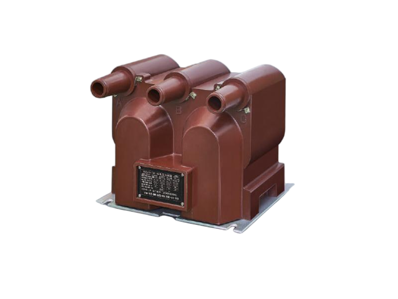
For Zero Sequence Current Transformer used in ground fault detection, the ratio test is especially important because even small deviations can affect protection performance.
For example, a 1000:5 current transformer should produce 5A when 1000A flows in the primary. If you apply 100A to the primary, you should see about 0.5A on the secondary.
If the measured ratio deviates significantly from the rated ratio, the current transformer may have a problem. Small deviations may be acceptable depending on the accuracy class.
Secondary Injection Test
Secondary injection is another practical approach. It is useful when you cannot energize the primary side.
Steps:
- Disconnect the secondary wires from the connected devices
- Inject a known current into the secondary circuit
- Check if the connected meter or relay reads correctly
This method tests the entire secondary circuit, not just the current transformer. It reflects actual operating conditions more closely.
Insulation Resistance Test
Safety is also part of checking a current transformer. Insulation resistance should be high.
Steps:
- Disconnect all external wiring
- Use an insulation resistance tester (500V or 1000V, depending on the Current Transformer rating)
- Measure between primary and secondary, and between each winding and ground
- Compare with standard values (typically above 100 megohms)
Low insulation resistance indicates moisture ingress or insulation degradation. A current transformer with low insulation resistance should be replaced.
Summary of Methods
The table below summarizes the main methods for checking a current transformer.
| Method | What It Checks | What to Look For |
|---|---|---|
| Visual inspection | Physical condition | Cracks, burns, loose parts |
| Secondary winding test | Winding continuity | Open or short circuit |
| Polarity check | Output direction | Correct orientation |
| Ratio test | Accuracy | Large deviation from rated ratio |
| Secondary injection | System response | Correct meter or relay reading |
| Insulation test | Safety | Low resistance reading |
Practical Considerations
Even when following all the steps, real conditions are not always ideal.
Sometimes:
- Full shutdown is not possible for safety or operational reasons
- Testing time is limited
- Results are not perfectly clear
Because of this, multiple methods are usually combined. A visual check alone is not enough. A ratio test without a polarity check may miss a wiring issue.
Also, not every deviation requires replacement. A current transformer can still operate within acceptable limits. Understanding those limits is just as important as performing the tests.
For critical systems, keep records of test results over time. A slow drift in ratio or insulation resistance may indicate gradual degradation. This helps you plan replacement before failure occurs.

Conclusion
So how do you check if a current transformer is working?
There is no single method that gives a complete answer. Instead, it involves:
- Visual inspection
- Winding resistance measurement
- Polarity verification
- Ratio testing
- Insulation resistance checking
In most cases, problems develop gradually, not suddenly. That is why regular checking helps maintain system stability.
If something feels slightly unusual, even without clear evidence, it is worth checking. A few minutes of testing can prevent hours of troubleshooting later.
Different types of current transformers like High Voltage Current Transformer, Low Voltage Current Transformer, and Zero Sequence Current Transformer all benefit from these same basic checks.
FAQ
Can a current transformer give correct readings even if it has minor issues?
Yes, minor issues may not immediately affect readings. But accuracy can degrade over time. Regular checks help catch problems before they become serious.
Is advanced testing equipment always required for checking a current transformer?
No. A multimeter and clamp meter are usually enough for basic checks like resistance and polarity. Advanced equipment is only needed for ratio or saturation tests.
How often should a current transformer be tested?
It depends on the application and operating conditions. For critical systems, annual checks are common. For less critical systems, every two to three years may be enough. Always follow manufacturer recommendations.