In many power systems, especially in industrial environments, improving power factor is often considered a routine optimization step rather than a one-time adjustment. However, when the objective shifts toward correcting power factor to unity, the discussion usually becomes more practical and situation-based.
A power factor close to unity means that electrical energy is being used efficiently, with minimal reactive losses. In theory, reaching a power factor of 1 suggests that all supplied power is effectively converted into useful work. In reality, though, this condition is rarely stable for long periods. System loads change, equipment operates intermittently, and reactive power demand fluctuates throughout the day.
Because of these variations, correcting power factor to unity is often approached as a dynamic process rather than a fixed target. In many installations, maintaining a stable and high power factor—rather than perfect unity—is considered sufficient for achieving noticeable improvements in system performance.
Table of Contents
Understanding Power Factor and Unity
What is Power Factor
Power factor represents the relationship between active power and apparent power. It indicates how efficiently electrical energy is being utilized in a system.
A simplified interpretation:
- Power factor = 1 → maximum efficiency
- Power factor < 1 → part of the energy is reactive
In practical systems, power factor is influenced by the types of loads connected to the network. Inductive loads tend to reduce power factor, while capacitive elements can improve it.
What Unity Means in Real Systems
Correcting power factor to unity means aligning current and voltage so that reactive power is minimized. However, achieving this condition continuously is difficult due to system variability.
In many real-world situations:
- Load demand changes throughout operation
- Equipment cycles on and off
- Reactive power requirements shift over time
Because of this, many systems aim for a power factor close to unity, typically between 0.95 and 0.99. This range is often sufficient to achieve most efficiency benefits without introducing instability.
Causes of Low Power Factor
Inductive Loads
The most common cause of low power factor is the presence of inductive equipment.
Examples include:
- Electric motors
- Transformers
- Industrial machinery
These devices require reactive power to operate, which reduces the overall power factor of the system.
Load Variability
In many installations, loads are not constant.
Typical scenarios include:
- Equipment starting and stopping frequently
- Production processes changing over time
- Seasonal or operational variations
This variability makes power factor correction in industrial systems more complex than a simple one-time calculation.
Distribution System Characteristics
In some cases, the layout of the power distribution system itself contributes to low power factor.
Factors such as:
- Long cable runs
- Uneven load distribution
- Aging infrastructure
can influence how reactive power behaves in the system.
Methods to Correct Power Factor to Unity
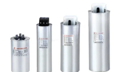
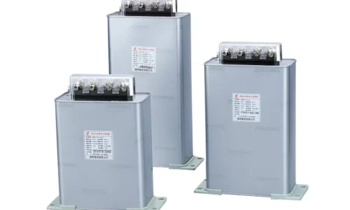
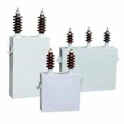
Capacitor Banks
The most widely used method to improve power factor is the installation of capacitor banks.
Capacitors supply reactive power locally, reducing the demand for reactive power from the source. This leads to improved system efficiency.
Typical effects include:
- Reduced current flow
- Lower energy losses
- Improved voltage conditions
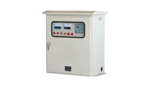
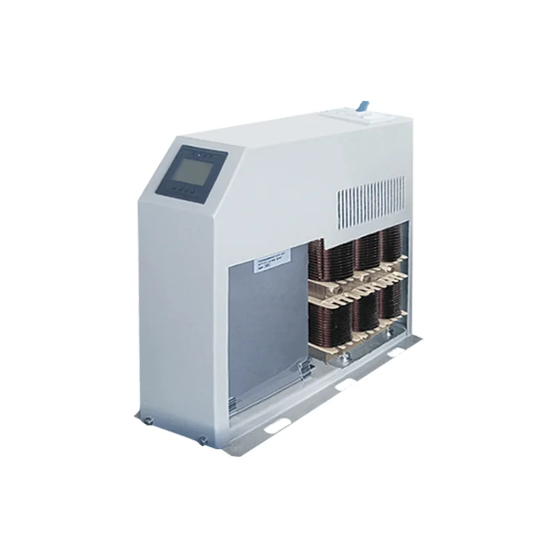
Automatic Power Factor Correction Systems
In systems where load conditions change frequently, automatic correction systems are commonly used.
These systems:
- Continuously monitor power factor
- Automatically switch capacitor banks
- Adjust compensation levels based on demand
This allows the system to maintain power factor close to unity under varying conditions.
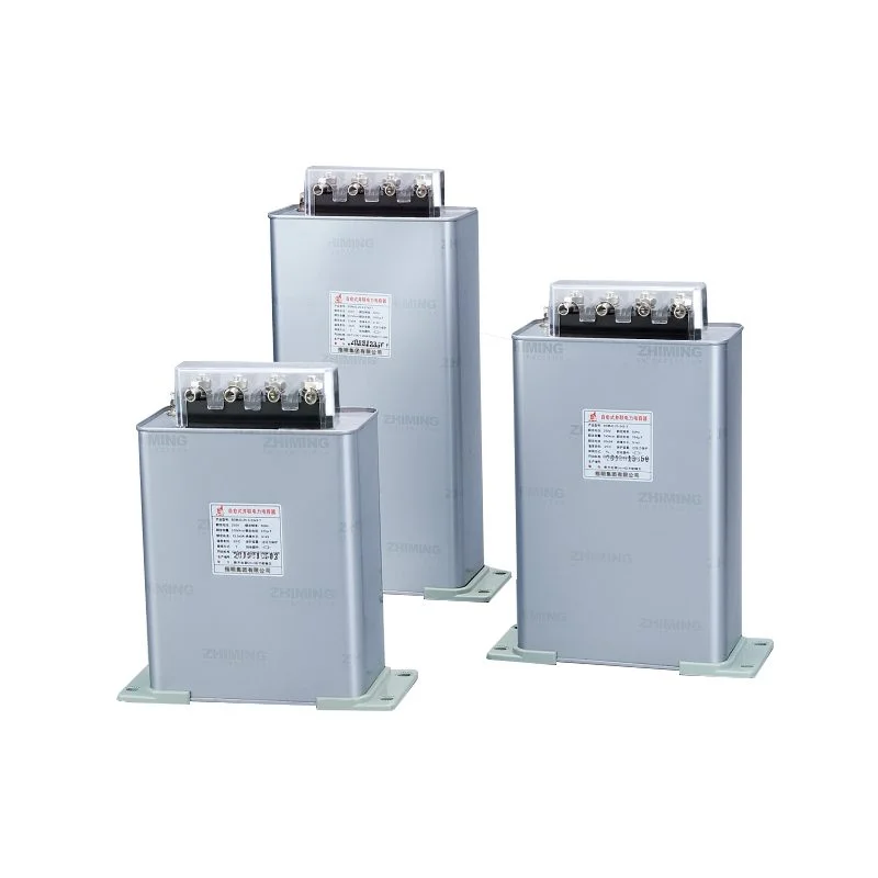
Selecting Suitable Capacitors
Different capacitor types are used depending on system requirements:
- Low Voltage Power Capacitor for standard distribution systems
- High Voltage Power Capacitor for large-scale networks
- HV Single Phase Power Capacitor for specific applications
Selecting the correct capacitor type is essential for effective power factor correction.
Step-by-Step Approach to Correction
In practical applications, correcting power factor to unity often involves several steps.
A typical process includes:
- Measure existing power factor
- Analyze reactive power demand
- Calculate required compensation capacity
- Select appropriate capacitor equipment
- Install and monitor system performance
This process may be adjusted depending on system complexity and operational requirements.
Benefits of Improving Power Factor
Reduction of Energy Losses
Improving power factor reduces current flow in the system, which decreases losses in cables and transformers.
Improved Voltage Stability
A higher power factor helps maintain more stable voltage levels, especially in systems with fluctuating loads.
Better Utilization of Equipment
With improved power factor:
- Equipment operates more efficiently
- System capacity is better utilized
- Risk of overheating is reduced
Performance Comparison
| Condition | Low Power Factor | Near Unity Power Factor |
|---|---|---|
| Current Flow | Higher | Lower |
| Energy Loss | Increased | Reduced |
| Voltage Stability | Less stable | More stable |
| Efficiency | Lower | Higher |
Challenges in Achieving Unity Power Factor
Overcompensation
In some cases, excessive correction may result in a leading power factor, which can affect voltage stability.
Dynamic Load Conditions
Frequent changes in load demand make it difficult to maintain a constant power factor.
System Limitations
Existing infrastructure may limit how precisely power factor can be controlled.
Additional Practical Observations
In real installations, correcting power factor to unity is rarely an immediate transformation. At first, system behavior may appear unchanged, especially if the previous power factor was not extremely low.
Over time, however, certain improvements become noticeable. Energy losses tend to decrease slightly, voltage fluctuations become less pronounced, and equipment operates more consistently. These changes are often gradual and may not be immediately attributed to power factor correction.
In systems with frequent load variation, maintaining power factor close to unity requires continuous adjustment. Automatic systems help manage this process, but even then, perfect unity is not always maintained. Instead, stability and consistency become the primary goals.
Conclusion
Correcting power factor to unity is an important objective in improving electrical system efficiency, even though maintaining perfect unity continuously may not always be practical.
By using capacitor banks and automatic correction systems, it is possible to improve power factor, reduce losses, and enhance system performance. Over time, these improvements contribute to more stable operation and better utilization of electrical infrastructure.
FAQ
Can power factor correction reduce transformer load?
Yes, improving power factor reduces current, which lowers the load on transformers.
Is automatic correction necessary for all systems?
Not always, but it is recommended for systems with frequent load changes.
Can power factor correction improve voltage regulation?
Yes, better power factor helps maintain more stable voltage levels.