Power factor correction sounds technical — and it is — but the underlying concept is surprisingly straightforward once you get past the terminology. Industrial facilities, commercial buildings, and even some residential installations use capacitor bank systems to improve electrical efficiency and reduce utility costs.
The basic idea? Most electrical loads draw more current than they actually need to perform useful work. A capacitor bank compensates for this inefficiency by supplying reactive power locally, reducing the burden on the electrical supply system.
Understanding how this works requires a bit of background on what power factor actually means and why utilities care about it enough to penalize customers with poor power factor.

Table of Contents
Understanding Power Factor Before Capacitor Bank Correction
What Power Factor Actually Represents
In AC electrical systems, voltage and current waveforms ideally rise and fall together — perfectly synchronized. When this happens, power factor equals 1.0 (or 100%), and all the current flowing actually performs useful work.
Real-world loads mess this up. Inductive loads — motors, transformers, fluorescent lighting ballasts — cause current to lag behind voltage. The current still flows, conductors still heat up, and the utility still has to generate and transmit it. But some of that current just sloshes back and forth without doing productive work.
Power factor measures the ratio of real power (the useful stuff) to apparent power (the total current flow). A power factor of 0.7 means only 70% of the current is actually working. The rest is reactive current — necessary to establish magnetic fields in inductive equipment but not directly performing useful work.
Why Low Power Factor Matters
From a utility perspective, low power factor means transmitting current that doesn’t generate revenue. Lines, transformers, and generators all have to be sized for the apparent power, not just the real power customers pay for.
Consequences of poor power factor include:
- Utility penalty charges on commercial and industrial accounts
- Increased conductor losses (I²R heating)
- Reduced system capacity for actual productive loads
- Voltage drop issues on distribution systems
- Oversized electrical infrastructure requirements
How a Capacitor Bank Provides Power Factor Correction
The Compensation Principle
Here’s where capacitors become useful. While inductive loads cause current to lag voltage, capacitors cause current to lead voltage. A capacitor bank introduces leading reactive current that cancels the lagging reactive current from inductive loads.
Think of it as balancing. The inductive load pulls current one direction relative to voltage timing. The capacitor bank pulls it the opposite direction. Combined, they neutralize each other’s reactive effects, and the supply system sees something much closer to unity power factor.
The key point — and this is worth emphasizing — the capacitor bank doesn’t reduce the reactive power that motors and transformers need. Those devices still draw their reactive current. The capacitor bank simply supplies that reactive current locally instead of forcing the utility to supply it through the distribution system.
Power Factor | Reactive Power Demand | Capacitor Bank Benefit |
0.70 lagging | High | Major correction needed |
0.85 lagging | Moderate | Noticeable improvement achievable |
0.95 lagging | Low | Fine-tuning correction |
1.00 unity | None | No correction required |
Fixed vs. Automatic Capacitor Bank Systems
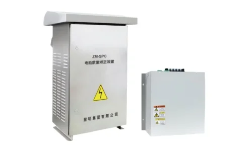
High voltage capacitor bank installations typically come in two basic configurations:
Fixed capacitor banks that provide constant reactive power compensation.
Automatic switching banks that adjust compensation based on actual demand.
Fixed high voltage power capacitor systems work well when load characteristics remain stable. A facility running the same motors at constant load can install fixed capacitors sized for that specific reactive demand.
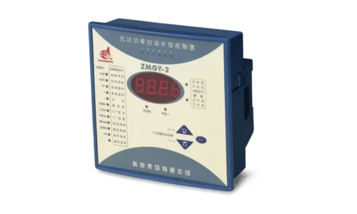
Automatic high voltage power capacitor systems suit variable loads better. A controller monitors the power factor continuously and switches capacitor stages in or out to match changing conditions. This prevents over-correction—which can create a leading power factor and its own set of problems—while maintaining the target power factor across varying operating conditions.
Benefits of Capacitor Bank Installation
Economic and Technical Advantages
Installing a capacitor bank for power factor correction delivers both immediate and ongoing benefits:
- Elimination or reduction of utility power factor penalties
- Released system capacity for additional loads
- Reduced line losses throughout the facility
- Improved voltage regulation at load points
- Extended equipment life due to reduced current stress
- Potential deferral of transformer and cable upgrades
The economic payback often surprises facility managers. Power factor penalties can represent significant monthly costs, and capacitor bank installations frequently pay for themselves within one to three years — sometimes faster for heavily penalized accounts.
Proper Sizing Considerations
A capacitor bank sized incorrectly creates problems. Undersized banks leave power factor penalties on the table. Oversized banks push power factor leading, potentially causing voltage rise, resonance issues, and different utility penalties.
Proper sizing requires:
- Measuring actual reactive power demand across operating conditions
- Identifying target power factor (typically 0.95 to 0.98)
- Calculating required capacitor kVAR rating
- Considering load variation and whether automatic switching is needed
- Evaluating harmonic levels that might affect capacitor bank performance
FAQ
What size capacitor bank is needed to correct power factor?
Required capacitor bank size depends on the existing power factor, target power factor, and real power consumption. The calculation uses kVAR (kilovolt-ampere reactive) ratings. Most electrical engineers use tables or formulas relating these variables. As a rough example, correcting a 500 kW load from 0.75 to 0.95 power factor requires approximately 285 kVAR of capacitor bank compensation. However, actual installations should be based on measured data rather than estimates, since load characteristics vary significantly between facilities. Professional power quality analysis before installation ensures proper sizing and avoids both under-correction and over-correction problems.
Can a capacitor bank cause problems on electrical systems?
Yes, improperly applied capacitor banks can create issues. Harmonic resonance — where capacitor bank reactance interacts with system inductance at harmonic frequencies — can amplify harmonic distortion and damage equipment. Switching transients when capacitor banks energize can cause voltage spikes. Over-correction creates leading power factor with its own technical and billing consequences. These problems are avoidable with proper engineering, including harmonic analysis, appropriate switching controls, and correct sizing. Most issues arise from installations that skip the analysis step and simply guess at capacitor bank requirements.
How long does a capacitor bank last before replacement?
Quality capacitor bank installations typically last 15-20 years under normal operating conditions. Actual lifespan depends on factors including ambient temperature, switching frequency, harmonic exposure, and manufacturing quality. Capacitors gradually lose capacitance over time, reducing correction effectiveness before outright failure. Regular inspection and occasional capacitance testing help identify degradation before it affects power factor significantly. Harsh environments — high temperatures, heavy harmonics, frequent switching — shorten life expectancy and may justify premium capacitor grades designed for demanding conditions.