Table of Contents
The Purpose Behind APFC Panel Installation in Modern Facilities
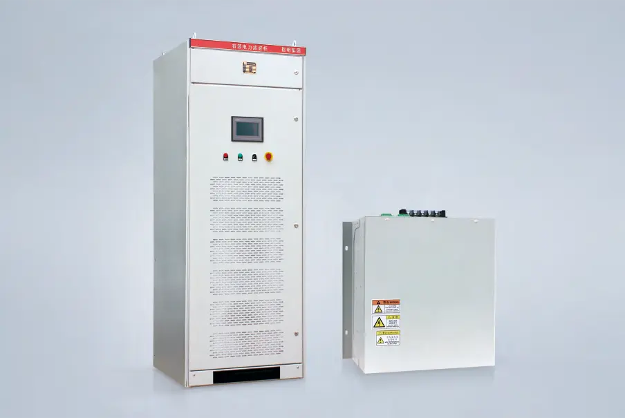
Walk through any large industrial facility and somewhere—usually near the main switchboard—sits an enclosure quietly doing critical work. The APFC panel doesn’t attract much attention during normal operations. No moving parts visible from outside, no dramatic sounds. Just steady, automatic correction happening behind closed doors.
But remove it, and problems surface quickly. Utility penalties climb. Transformers run hotter than they should. Voltage fluctuates more noticeably. The unassuming cabinet proves essential once it’s gone.
APFC stands for Automatic Power Factor Correction. These panels monitor electrical conditions continuously and adjust capacitor banks to maintain target power factor levels. Unlike fixed correction systems that provide constant reactive power regardless of conditions, an APFC panel responds dynamically to changing loads throughout the day.
The technology isn’t new exactly, but it’s become increasingly sophisticated. Modern units offer programmable logic, communication capabilities, and harmonic filtering options that older systems lacked entirely.
How an APFC Panel Functions
The Automatic Correction Process
Inside the panel, a controller serves as the brain of the operation. This device measures current and voltage from the electrical system, calculates the existing power factor, and compares it against programmed targets.
When power factor drops below the setpoint—say, falls to 0.85 when 0.95 is desired—the controller activates capacitor stages to inject compensating reactive power. If loads decrease and power factor climbs too high, stages disconnect to prevent overcorrection.
The whole sequence happens automatically. No operator intervention required.
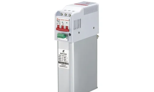
Key Components Within the Enclosure
A typical APFC panel contains several essential elements working together:
- Intelligent power factor controller (the decision-making unit)
- Multiple capacitor stages, often three-phase configurations
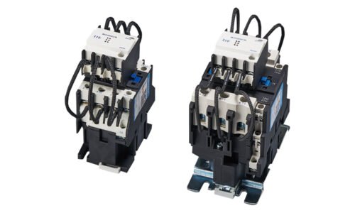
- Switching contactors or thyristors for each stage
- Individual stage protection through fuses or MCBs
- Indicating lamps showing active stages
- Main incoming breaker for isolation
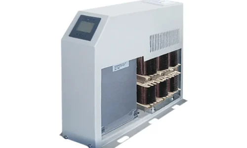
- Sometimes detuning reactors for harmonic management
Higher-quality panels include features like surge protection, temperature monitoring, and communication ports for remote access. These additions increase cost but provide genuine value in critical applications.
Reasons Why APFC Panel Systems Are Essential
Eliminating Power Factor Penalties
This is usually the primary motivator. Utility companies measure power factor—the ratio of useful power to total apparent power—and charge penalties when it falls below acceptable thresholds.
These penalties aren’t trivial either. Large facilities operating at 0.8 power factor might see surcharges adding 10-20% to electricity bills. Some rate structures penalize even more aggressively.
An APFC panel maintains power factor above penalty thresholds automatically. The investment typically pays for itself within two to four years through penalty elimination alone.
Responding to Variable Load Conditions
Fixed capacitor banks work acceptably when loads stay constant. But real facilities rarely operate that way. Shifts change. Production lines start and stop. Seasonal demands fluctuate.
Without automatic adjustment, fixed correction leads to problems:
- Undercorrection during heavy load periods
- Overcorrection when loads drop
- Leading power factor that utilities may also penalize
- Potential voltage rise damaging sensitive equipment
The APFC panel solves these issues by continuously adapting correction levels to actual conditions.
Maximizing Electrical Infrastructure
Reactive current occupies capacity in cables, transformers, and switchgear without producing useful output. When an APFC panel reduces this reactive component, existing infrastructure can handle more real power.
Consider a transformer rated for 1000 kVA operating at 0.8 power factor. Only 800 kW of real power reaches connected loads. Improve power factor to 0.95 and that same transformer delivers 950 kW—nearly 20% more useful capacity without any hardware upgrade.
For growing facilities, this released capacity can defer expensive infrastructure expansion significantly.
Improving System Voltage Profile
Reactive current flowing through cables and transformers causes voltage drops. Equipment located far from the main supply receives lower voltage than equipment nearby. Motors run slightly slower, less efficiently.
By reducing total current flow, APFC panel systems improve voltage stability throughout the distribution network. Equipment operates closer to design parameters.
Comparing APFC Panel Configurations
Feature | Basic APFC Panel | Standard APFC Panel | Advanced APFC Panel |
Number of stages | 4-6 | 8-12 | 12-16+ |
Controller type | Basic relay | Programmable | Smart with comms |
Harmonic handling | None | Optional detuning | Active filtering |
Monitoring | Local indicators | Digital display | Remote connectivity |
Typical application | Small commercial | Medium industrial | Large or critical loads |
Installation Considerations for APFC Panel Systems
Proper Sizing Matters
Undersized panels fail to achieve adequate correction. Oversized panels waste capital and risk overcorrection problems. Getting the size right requires actual load data—not estimates or nameplate ratings.
Measurements should capture:
- Existing power factor across different operating conditions
- Maximum reactive power demand in kVAR
- Load variation patterns during typical cycles
- Harmonic content if non-linear loads exist
Location Within the Facility
Centralized installation at the main switchboard improves overall power factor as seen by the utility. This approach uses a single APFC panel to correct the entire facility.
Distributed installation places smaller panels near major loads. This approach reduces losses within the internal distribution system but requires more equipment and coordination.
Many facilities use a combination—central correction for general loads plus local correction at large motors or problematic areas, or even an active power filter panel cabinet for harmonic mitigation in critical spots.

Environmental Factors
Heat affects capacitor life significantly. An APFC panel installed in a hot, poorly ventilated location will fail sooner than one in controlled conditions. Adequate clearance and airflow around the enclosure extends service life.
Dust, humidity, and corrosive atmospheres also pose challenges. Appropriate enclosure ratings (IP protection) should match installation conditions.
Common Applications for APFC Panel Technology
These systems appear across diverse settings:
- Manufacturing plants with variable motor loads
- Commercial buildings with HVAC systems
- Data centers requiring reliable power quality
- Hospitals and healthcare facilities
- Water treatment and pumping stations
- Shopping malls and large retail complexes
Anywhere significant inductive loads operate with varying demand, an APFC panel typically makes sense.
FAQ
How many capacitor stages should an APFC panel have?
Stage count depends on load variation and required correction resolution. Facilities with highly variable loads benefit from more stages (10-16) providing finer adjustment. Stable loads may need only 6-8 stages for adequate control.
Can an APFC panel operate in harmonic-rich environments?
Standard panels may experience problems with harmonics including resonance and capacitor failure. Detuned configurations add series reactors that prevent resonance. Facilities with significant harmonic distortion should specify detuned or active filter solutions.
What maintenance does an APFC panel require?
Annual inspection is typically recommended. Technicians verify capacitor condition, check contactor operation, tighten connections, and confirm controller calibration. Capacitors generally require replacement after 10-15 years depending on operating conditions.