Capacitors show up in virtually every power supply circuit ever designed. Open any switching power supply, linear regulator, or even a simple battery charging circuit — capacitors are there, often multiple types doing different jobs. Their presence is so universal that it’s easy to overlook what they’re actually doing.
But here’s the thing. Remove or undersize a capacitor for power supply applications and the circuit misbehaves in ways that range from annoying ripple to complete instability. These components aren’t optional extras or afterthoughts. They’re fundamental to how power supplies actually function.
Understanding what capacitors contribute to power supply design helps explain why certain capacitor types get selected, why values matter, and why failures in these positions cause so much trouble.
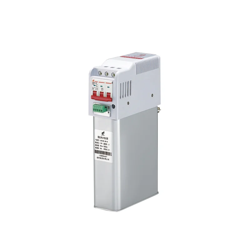
Table of Contents
Primary Functions of a Capacitor for Power Supply Circuits
Filtering and Smoothing Voltage
This is probably the most recognized function. Rectified AC voltage comes out lumpy — full of peaks and valleys that would wreak havoc on sensitive electronics. A capacitor for power supply filtering absorbs energy during voltage peaks and releases it during valleys, smoothing the waveform into something closer to steady DC.
The smoothing isn’t perfect. Some ripple remains, and the amount depends on capacitor size, load current, and ripple frequency. But the difference between unfiltered rectified AC and properly filtered DC is dramatic. Loads that need clean voltage — microprocessors, audio circuits, precision analog — simply won’t work correctly without adequate filtering capacitance.
Energy Storage During Load Transients
Power supplies don’t always see steady loads. Digital circuits switch states rapidly. Motors start and stop. Communication bursts draw sudden current. These transient demands can outpace the power supply’s ability to respond instantly.
Capacitors bridge the gap. They store energy locally and release it during sudden demand spikes faster than the main power supply can react. Without sufficient capacitance, voltage droops during transients — potentially causing resets, data corruption, or erratic behavior in connected circuits.
Decoupling and Noise Suppression
High-frequency noise rides on power rails constantly. Switching regulators generate it inherently. Digital circuits create noise as gates toggle. External interference couples in through various paths. This noise needs somewhere to go besides into sensitive circuit nodes.
A capacitor for power supply decoupling provides a low-impedance path for high-frequency noise, shunting it to ground before it causes problems. The capacitor essentially acts as a short circuit for noise frequencies while appearing as an open circuit to DC power.
Decoupling effectiveness depends heavily on capacitor type and placement:
- Ceramic capacitors excel at high-frequency decoupling due to low ESR and ESL
- Placement close to IC power pins minimizes parasitic inductance
- Multiple small capacitors often outperform single large ones for broadband noise
- Different capacitor values target different frequency ranges
Types of Capacitors Used in Power Supply Applications
Choosing the Right Capacitor for Power Supply Needs
Capacitor Type | Typical Capacitance Range | Key Characteristics | Common Power Supply Role |
Aluminum Electrolytic | 1µF – 10,000µF | High capacitance, moderate ESR, polarized | Bulk filtering, energy storage |
Ceramic (MLCC) | 1pF – 100µF | Low ESR/ESL, stable, non-polarized | High-frequency decoupling, output filtering |
Film (Polypropylene, Polyester) | 100pF – 100µF | Low loss, high voltage capability, stable | Input filtering, snubbing, resonant circuits |
Tantalum | 0.1µF – 1000µF | Moderate ESR, compact, polarized | Compact bulk filtering, output stabilization |
Polymer Electrolytic | 10µF – 1000µF | Low ESR, improved reliability | Output filtering in switching supplies |
Combining Capacitor Types
Real power supply designs almost always combine multiple capacitor types, scaling from compact boards to industrial systems. A typical switching regulator output might use:
Large electrolytic capacitors for bulk energy storage and low-frequency ripple reduction
Polymer capacitors for moderate-frequency filtering with better ESR than standard electrolytics
Small ceramic capacitors for high-frequency noise suppression
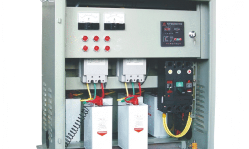
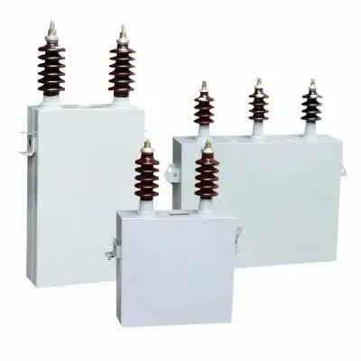
This combination addresses different frequency ranges that no single capacitor type handles optimally across the entire spectrum. Similarly, in industrial power conditioning or heavy-duty applications, a three phases high-voltage power capacitor bank is often employed to stabilize grid-level voltage, correct power factor, and filter harmonic noise across all three phases—serving a parallel principle of tailored capacitance for specific electrical demands at a much higher power scale.
Common Applications of Capacitor for Power Supply Design
Linear Regulator Input and Output
Linear regulators need capacitors at both input and output, though for somewhat different reasons. Output capacitors stabilize the regulator feedback loop and provide local energy storage for load transients. Input capacitors prevent source impedance from causing instability and reduce ripple reaching the regulator.
Most linear regulator datasheets specify minimum and maximum capacitance ranges along with ESR requirements. Ignoring these specifications — particularly on low-dropout regulators — often results in oscillation or degraded transient response.
Switching Power Supply Filtering
Switching supplies operate at frequencies from tens of kilohertz to several megahertz. The switching action inherently generates ripple and noise at these frequencies plus harmonics. A capacitor for power supply filtering in switching applications must handle:
- Fundamental switching frequency ripple
- High-frequency switching transients
- Conducted EMI that could propagate to input or output
The combination typically involves bulk capacitance for energy storage plus low-ESR capacitors for high-frequency performance. Output capacitor selection directly affects output ripple voltage, transient response, and control loop stability.
Input Filtering and Inrush Limiting
Input capacitors on power supplies serve dual purposes. They filter incoming voltage ripple (especially when fed from rectified AC) and provide local energy storage for input current pulses in switching converters. Large input capacitance creates an inrush current problem at startup — the uncharged capacitor looks momentarily like a short circuit.
Balancing these factors requires considering:
- Required holdup time during input interruptions
- Acceptable inrush current magnitude
- Input ripple current rating of selected capacitors
- Available space and cost constraints
FAQ
What size capacitor is needed for power supply filtering?
The required capacitance depends on load current, acceptable ripple voltage, and ripple frequency. A rough starting calculation uses the formula C = I / (f × ΔV), where I is load current, f is ripple frequency, and ΔV is acceptable ripple voltage. For example, a 1A load at 120Hz ripple (full-wave rectified 60Hz) with 1V acceptable ripple needs approximately 8,300µF. Practical designs then adjust based on capacitor ESR contribution to ripple, transient requirements, and available component values. Most power supply controller datasheets provide specific capacitor selection guidance for their particular topology. Following manufacturer recommendations — then validating with actual ripple measurements — produces better results than pure calculation.
Can any capacitor be used for power supply applications?
No. A capacitor for power supply use must handle the specific voltage, ripple current, temperature, and frequency conditions present. Using a capacitor rated for lower voltage risks catastrophic failure. Using a capacitor with inadequate ripple current rating causes overheating and premature degradation. Ceramic capacitors with certain dielectrics lose substantial capacitance under DC bias — a critical consideration when filtering power rails.
Why do switching power supplies need multiple capacitors?
Switching converters operate across a wide frequency range and no single capacitor type performs optimally everywhere. Electrolytic capacitors provide bulk capacitance economically but exhibit high impedance at switching frequencies due to ESR and ESL. Ceramic capacitors offer excellent high-frequency performance but become expensive and physically large at high capacitance values. Combining types — electrolytics for low-frequency energy storage, ceramics for high-frequency filtering — delivers better overall performance than either alone.