Table of Contents
Exploring What SVC Technology Does in Power Systems
Some equipment works invisibly. It operates day and night, responding to conditions most people never notice, preventing problems that would otherwise cause real disruption. Static VAR Compensators fall into this category.
An SVC sits at substations or industrial facilities, monitoring electrical conditions and adjusting reactive power output continuously. When voltage sags, it responds. When power factor drifts, it corrects. When rapid load changes threaten stability, it compensates almost instantly.
The technology has been around since the 1970s, actually. Thyristor-based power electronics made it possible to control large amounts of reactive power without mechanical switching—hence the “static” designation. No rotating parts. No contactors opening and closing constantly. Just solid-state devices handling the heavy lifting.
Understanding what SVC systems accomplish requires grasping why reactive power matters. And it matters quite a bit, even though it doesn’t show up directly on electricity bills for most consumers.
Core Applications of SVC Systems
Voltage Regulation Across Networks
Transmission systems operate within tight voltage tolerances. Too low means poor power quality and potential equipment malfunction. Too high risks insulation breakdown and premature failure.
An SVC maintains voltage by dynamically controlling reactive power flow. The physics works like this: injecting reactive power (capacitive mode) raises local voltage, while absorbing reactive power (inductive mode) lowers it. The SVC does both, switching seamlessly between modes as conditions require.
Response happens in milliseconds—not the seconds required by mechanical switching or the minutes needed for generator adjustments. This speed proves essential during disturbances when voltage might otherwise collapse before slower controls could react.
Power Factor Correction at Industrial Sites
Heavy industry runs on motors. And motors, along with transformers and similar equipment, create lagging power factor by drawing reactive current from the supply. Utilities measure this and charge penalties when power factor falls below acceptable levels.
The financial motivation alone drives many SVC installations. Consider a facility paying thousands monthly in power factor penalties. An SVC corrects power factor automatically across varying load conditions, eliminating those charges essentially overnight.
But the benefits extend beyond bill reduction:
- Lower current flow through cables and transformers
- Reduced electrical losses throughout the distribution system
- Increased available capacity in existing infrastructure
- Better voltage at equipment terminals
- Extended lifespan for overworked components
Flicker Mitigation for Problem Loads
Arc furnaces cause headaches. So do large motors starting frequently, welding operations, and various other fluctuating loads. They create rapid voltage variations that propagate through networks, causing visible flicker in lighting and potentially affecting sensitive equipment.
An SVC tracks these rapid variations and injects compensating reactive power to smooth out voltage fluctuations. The response must be fast—faster than the load changes causing the problem—which is exactly where thyristor-based technology excels.
Steel mills commonly install SVC systems specifically for flicker control. Without them, complaints from neighboring customers would create ongoing problems with utility relationships.
Grid Stability Enhancement
Power systems operate closer to their limits than many realize. Margins for error have shrunk as demand grows and new generation connects. Stability concerns—both transient and voltage-related—require careful management.
SVC technology helps by providing dynamic reactive support during disturbances. When faults occur, an SVC responds within cycles to support voltage recovery. When large loads trip suddenly, it adjusts to prevent overvoltage. During system oscillations, properly tuned systems can provide damping to restore stable operation faster.
Utilities position these devices strategically at weak points in transmission networks, effectively strengthening the grid without building new lines.
How an SVC System Works
The Main Building Blocks
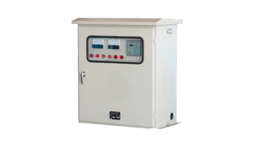
A typical SVC combines several elements:
- Thyristor-controlled reactor (TCR) for continuously variable reactive absorption
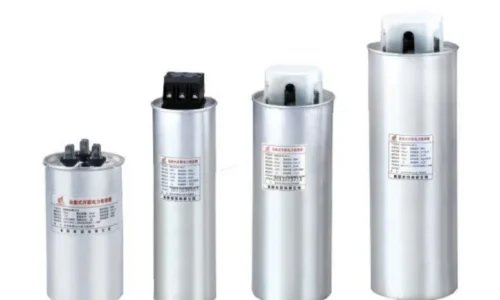
- Thyristor-switched capacitor banks (TSC) for stepped reactive injection
- Fixed capacitor banks and filters for harmonic management
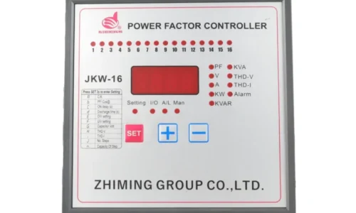
- Control system processing measurements and determining output
- Cooling systems—air or water depending on size
- Protection equipment monitoring for internal faults
The TCR portion uses back-to-back thyristors to control current flow through large reactors. By adjusting the firing angle, current varies from zero to full rating smoothly. This provides the continuous variability that distinguishes SVC from simple switched capacitor banks.
Control Philosophy
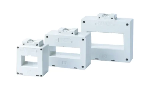
Modern SVC controllers measure voltage, current, and power factor from the point of connection. Algorithms calculate required output based on these measurements and programmed setpoints.
The control loop operates continuously:
- Sample electrical quantities multiple times per cycle
- Calculate present operating point
- Compare against desired operating point
- Determine required reactive power change
- Send firing commands to thyristors
- Verify response and adjust as needed
Multiple control modes typically exist. Voltage regulation mode maintains specified voltage. Power factor mode targets specific power factor. VAR mode holds constant reactive power output. Operators select modes based on operational requirements.
Comparing SVC with Alternative Technologies
Characteristic | SVC | STATCOM | Switched Capacitors |
Response time | 20-30 ms | 5-10 ms | Seconds |
Output range | Wide, continuous | Wide, continuous | Stepped only |
Performance at low voltage | Reduced | Maintained | Reduced |
Harmonic generation | Some (TCR) | Minimal | None |
Space requirement | Large | Compact | Moderate |
Cost per MVAR | Medium | Higher | Lower |
Each technology fits different applications. An SVC offers proven reliability and reasonable cost for most utility and industrial needs. STATCOM provides superior performance where speed and footprint matter most. Switched capacitors handle steady loads economically but lack dynamic capability.
Where SVC Installations Make the Most Sense
Transmission Substations
Weak points in the grid benefit most from dynamic voltage support. Long transmission corridors, interconnection points between systems, and areas with limited generation often see SVC installations.
Heavy Industrial Facilities
Steel plants, aluminum smelters, mining operations, and large manufacturing complexes frequently install SVC systems. The combination of power factor correction, flicker control, and voltage improvement addresses multiple needs simultaneously.
Renewable Integration Points
Wind farms and solar installations require reactive power capability to meet grid codes. While modern inverters provide some capability, supplementary SVC systems may be needed for large installations or weak grid connections.
Railway Traction Systems
Electric railways create highly variable, sometimes unbalanced loads. An SVC installation at traction substations smooths out these variations and maintains acceptable power quality for neighboring utility customers.
Maintenance Considerations for SVC Equipment
These systems require regular attention to maintain reliability:
- Thyristor cooling systems need periodic inspection
- Capacitor banks degrade over time and require testing
- Control system software may need updates
- Filter components require condition monitoring
- Protection settings should be reviewed periodically
Well-maintained installations commonly operate 25-30 years. Neglected systems fail earlier and often at the worst possible times. If you want to know more about SVC, please read What is a VAR compensator used for.
FAQ
What does SVC stand for in electrical engineering?
SVC stands for Static VAR Compensator. “Static” indicates no moving parts (unlike synchronous condensers), while “VAR” refers to Volt-Ampere Reactive, the unit measuring reactive power that these systems control.
How quickly can an SVC respond to voltage changes?
Typical response times range from 20-30 milliseconds for full output change. This is fast enough for most grid disturbances but slower than newer STATCOM technology which responds in 5-10 milliseconds.
Is an SVC the same as a capacitor bank?
No. Capacitor banks provide fixed or switched reactive power in discrete steps. An SVC provides continuously variable reactive power that can both inject and absorb VARs, with much faster response and automatic control based on system conditions.