Table of Contents
Understanding What a VAR Compensator Does in Electrical Systems
Electricity grids face a constant balancing act. Voltage levels need to stay within acceptable ranges. Power factor should remain high enough to avoid inefficiency. And reactive power—the non-working component of electrical flow—must be managed carefully to prevent system problems.
A VAR compensator handles these challenges. VAR stands for Volt-Ampere Reactive, essentially the unit measuring reactive power. These devices inject or absorb reactive power as needed, maintaining electrical parameters within desired limits.
The applications range widely. Utility-scale systems stabilize transmission networks serving millions of customers. Industrial installations correct power factor and reduce penalty charges. Renewable energy facilities use them to meet grid connection requirements. The underlying technology varies, but the fundamental purpose remains consistent—controlling reactive power to improve electrical system performance.

Primary Applications of VAR Compensator Technology
Voltage Regulation and Stability
This might be the most critical function, particularly in transmission systems. Voltage tends to fluctuate based on load conditions, generation patterns, and network topology. Too high risks equipment damage. Too low causes performance problems and potential instability.
A VAR compensator maintains voltage by adjusting reactive power flow. When voltage drops, the device injects reactive power (acts capacitively) to boost it back up. When voltage rises excessively, it absorbs reactive power (acts inductively) to bring levels down.
The response speed matters here. Fast-acting compensators using power electronics can respond within milliseconds—essential for handling sudden disturbances like fault conditions or large load changes.
Power Factor Improvement
Industrial facilities often struggle with poor power factor. Motors, transformers, and other inductive equipment draw reactive current that doesn’t contribute to useful work but still occupies system capacity.
A VAR compensator generates leading reactive power to offset this lagging component. The result is higher power factor, which brings several practical benefits:
- Reduced or eliminated utility penalty charges
- Lower total current for given real power demand
- Released capacity in existing infrastructure
- Improved voltage at load locations
- Decreased transmission losses
For many industrial users, power factor improvement alone justifies the investment in VAR compensator equipment.
Grid Integration of Renewable Energy
Wind and solar installations present unique challenges for grid operators. Output varies with weather conditions. Some inverter technologies affect power quality. Grid codes require specific reactive power capabilities.
Modern VAR compensator systems help renewable facilities meet these requirements. They provide reactive power support independent of actual generation levels, helping maintain grid voltage stability even as renewable output fluctuates throughout the day.
Flicker Mitigation
Certain industrial processes—arc furnaces being the classic example—create rapid, irregular load variations that cause voltage fluctuations visible as light flicker. Beyond being annoying, severe flicker can trigger complaints from neighboring utility customers.
Fast-response VAR compensator technology tracks these rapid variations and injects compensating reactive power in real time. The voltage fluctuations are substantially reduced before they propagate through the network.
Types of VAR Compensator Systems
Static VAR Compensators (SVC)
The traditional workhorse of utility-scale reactive power compensation. Static VAR compensators combine thyristor-controlled reactors (TCRs) with thyristor-switched capacitors (TSCs) to provide continuous variable output.
TCR portions absorb reactive power by controlling current through reactor banks. TSC portions inject reactive power by switching capacitor banks. Together, they cover a wide operating range from fully inductive to fully capacitive.
Response times typically fall in the 20-30 millisecond range. Fast enough for most applications, though not ideal for the most demanding flicker control scenarios.
STATCOM Systems
Static synchronous compensators represent newer technology using voltage source converters instead of passive components. These devices essentially create an AC voltage source synchronized with the grid, injecting or absorbing reactive power based on voltage magnitude relative to the system.
STATCOM offers advantages over traditional static VAR compensator designs:
- Faster response—often under 10 milliseconds
- Better performance at reduced voltage levels
- Smaller physical footprint for equivalent capacity
- Independent control of real and reactive power
- Cleaner output with less harmonic content
The tradeoff involves higher cost per installed kVAR, though this gap has narrowed as power electronics prices decline.
Hybrid Configurations
Some installations combine technologies. A static VAR compensator might provide bulk reactive power capability while a smaller STATCOM handles fast transient response. This approach optimizes cost while delivering required performance.
VAR Compensator Type | Response Speed | Typical Capacity | Primary Applications |
SVC (thyristor-based) | 20-30 ms | 50-800 MVAR | Utility transmission, large industry |
STATCOM | 5-10 ms | 20-400 MVAR | Grid support, renewables, flicker |
Mechanically switched | Seconds | 10-200 MVAR | Steady-state correction only |
Hybrid systems | Varies | 100-1000+ MVAR | Complex utility applications |
Benefits of Installing VAR Compensator Equipment
Enhanced System Reliability
Voltage instability can cascade into widespread outages. By maintaining proper voltage profiles and providing dynamic reactive support, VAR compensator systems help prevent these cascading events. The investment in compensation often proves far cheaper than the economic cost of major blackouts.
Increased Transfer Capability
Transmission lines have thermal limits on current carrying capacity. But they also have stability limits related to voltage control and reactive power balance. These stability limits often restrict transfer capability before thermal limits come into play.
Strategic VAR compensator placement increases these stability margins. More power can flow through existing lines without triggering voltage problems. Infrastructure investment gets deferred.
Reduced Energy Losses
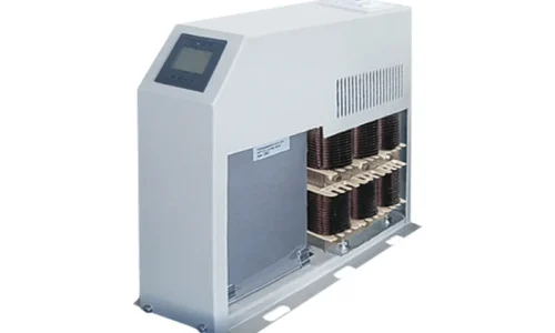
Reactive current flowing through transmission and distribution systems generates losses—the I²R heating effect in conductors. By providing reactive power locally rather than transmitting it from distant generators, VAR compensator installations, such as a low voltage power capacitor, reduce total current flow and associated losses.
The savings accumulate continuously over operating life. Even modest percentage reductions in losses translate to significant energy and cost savings over decades of operation.
Compliance with Grid Codes
Modern grid codes impose increasingly stringent requirements on connected facilities. Generators must provide reactive power capability. Large loads must maintain acceptable power factor. Interconnecting parties must demonstrate voltage control capability.
A VAR compensator helps facilities meet these requirements, avoiding penalties or connection refusal.
Choosing the Right VAR Compensator Solution
Selection depends on specific application requirements:
- Response speed needed for expected disturbances
- Total reactive power range required
- Space and installation constraints
- Harmonic environment and filtering needs
- Budget limitations and lifecycle cost considerations
- Future expansion possibilities
Detailed system studies typically precede major installations. These analyses model expected conditions and verify that proposed solutions will perform adequately.
FAQ
What is the difference between a VAR compensator and a capacitor bank?
Simple capacitor banks provide fixed reactive power output and cannot adjust to changing conditions. A VAR compensator dynamically varies its reactive power output based on system needs, providing much more precise control and faster response to disturbances.
How long does a VAR compensator installation typically last?
Major components like thyristors and capacitors typically have 20-30 year lifespans with proper maintenance. Control systems may require upgrades sooner as technology evolves. Overall, well-maintained installations commonly operate 25 years or longer.
Can a VAR compensator work with harmonic-polluted systems?
Yes, though design considerations apply. Some VAR compensator configurations include harmonic filtering as an integrated function. Others require detuning to prevent resonance with system harmonics. Proper specification accounts for expected harmonic conditions.