Table of Contents
Understanding Power Factor Correction Capacitor Basics
In industrial and commercial electrical systems, energy efficiency matters more than most people realize. When equipment runs inefficiently, it draws more current than necessary—and that costs money. This is where power factor correction capacitor technology comes into play, though the concept can seem a bit technical at first glance.
Power factor, put simply, is the ratio between real power (the power actually doing useful work) and apparent power (the total power drawn from the supply). A perfect power factor would be 1.0, but in reality, most facilities operate somewhere between 0.7 and 0.95. The gap represents wasted energy, mostly caused by inductive loads like motors, transformers, and certain lighting systems.
Three phase systems, commonly found in factories, large buildings, and manufacturing plants, face this challenge on a bigger scale. The three-phase configuration delivers power more efficiently than single-phase, but without proper correction, inefficiencies still creep in.
How 3 Phase Power Factor Correction Capacitors Work
The Role of Power Factor Correction Capacitors in Balancing Reactive Power
Inductive loads create what’s called “lagging” reactive power. Capacitors, interestingly enough, produce “leading” reactive power. When you install capacitors in a system, they essentially counteract the reactive component generated by inductive equipment.
Think of it like this—motors and transformers pull extra current that oscillates back and forth without performing actual work. Capacitors absorb and release energy in opposition, smoothing out these fluctuations. The result? Less strain on the electrical infrastructure and lower apparent power demand.
Components Found in Typical Systems
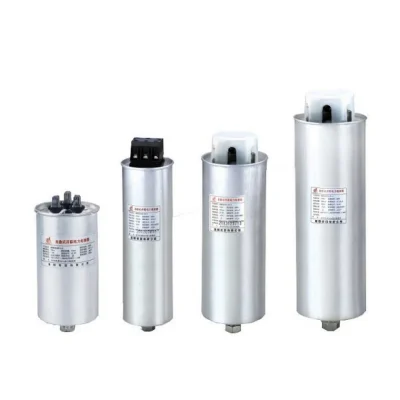
A three-phase correction unit usually contains several elements working together:
- Capacitor banks (often arranged in delta or star configurations)
- Contactors for switching capacitors in and out
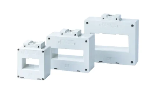
- Control relays that monitor power factor in real time
- Fuses or circuit breakers for protection
- Discharge resistors to safely dissipate stored energy
Some advanced units also include harmonic filters, which address distortion caused by non-linear loads like variable frequency drives.
Benefits of Installing Power Factor Correction Capacitors
Reduced Electricity Bills
Utility companies often charge penalties when power factor drops below a certain threshold—typically around 0.9 or so. By improving power factor, facilities can avoid these surcharges entirely. In some cases, the payback period for correction equipment is surprisingly short, sometimes less than two years.
Increased System Capacity
When reactive power decreases, the same cables and transformers can handle more real power. This frees up capacity without expensive infrastructure upgrades. For growing operations, that’s a significant advantage.
Extended Equipment Lifespan
Lower current flow means reduced heating in cables, switchgear, and transformers. Components run cooler, which generally translates to longer service life and fewer unexpected failures.
Benefit | Impact |
Lower utility penalties | Immediate cost savings |
Reduced current draw | Smaller cables and breakers needed |
Improved voltage stability | Better equipment performance |
Decreased I²R losses | Less wasted energy as heat |
Extended equipment life | Reduced maintenance expenses |
Types of 3 Phase Power Factor Correction Capacitor Systems
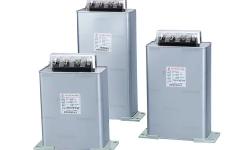
Fixed Capacitor Banks
These are the simplest option. A fixed bank provides constant reactive power compensation, making them suitable for facilities with stable, predictable loads. They’re less expensive upfront but lack flexibility.
Automatic Power Factor Correction Capacitor Units
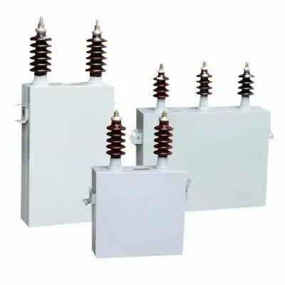
For operations where load varies throughout the day—and honestly, that describes most industrial settings—automatic systems make more sense. These units monitor the power factor continuously and switch high voltage power capacitor stages on or off as needed.
The controller measures real and reactive power, calculates the current power factor, and adjusts accordingly. This dynamic switching of high voltage power capacitors prevents overcorrection, which can actually cause leading power factor and create its own set of problems.
Detuned and Tuned Systems
In environments with significant harmonic distortion, standard capacitors can amplify harmonics rather than helping. Detuned reactors, installed in series with capacitors, shift the resonant frequency away from common harmonic frequencies. Tuned systems go further, actively filtering specific harmonic orders.
Installation Considerations
Proper installation involves more than just connecting wires. Site assessments should determine:
- Existing power factor during typical operation
- Load profile variations across shifts or seasons
- Presence of harmonic-producing equipment
- Available space for mounting equipment
- Ventilation requirements for heat dissipation
Skipping any of these steps can lead to undersized or oversized installations, neither of which delivers optimal results.
FAQ
What happens if a power factor correction capacitor fails?
Capacitor failure can result in reduced correction, blown fuses, or in severe cases, rupture and fire. Modern units include protective features like internal fuses and pressure-sensitive disconnects to minimize risks.
Can power factor correction capacitors cause harmonic problems?
Yes, in systems with significant harmonic distortion, capacitors can resonate with system inductance and amplify certain frequencies. Detuned or filtered systems address this concern effectively.
How often should power factor correction capacitor banks be inspected?
Annual inspections are generally recommended, though facilities with harsh operating conditions might benefit from more frequent checks. Signs of swelling, leakage, or discoloration indicate potential issues requiring attention.