Table of Contents
Why Improving Power Factor Matters for Electrical Systems
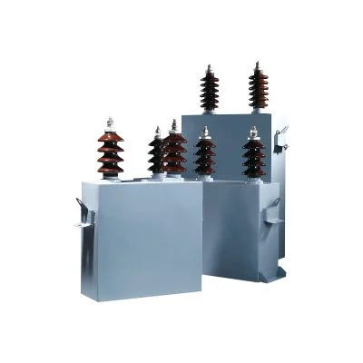
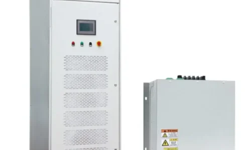
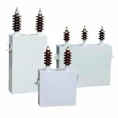
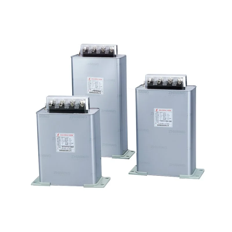
Method One: Capacitor Banks for Power Factor Correction
How Capacitors Correct Lagging Power Factor
Most industrial loads are inductive. Motors, transformers, fluorescent lighting ballasts—they all draw current that lags behind voltage. This lagging current creates the reactive power component that drags down power factor.
Capacitors do the opposite. They draw leading current that cancels out the lagging component from inductive loads. Install the right amount of capacitance, and the two reactive currents neutralize each other. The supply sees improved power factor as a result.
The physics isn’t complicated, really. It’s like adding weights to balance a scale. Too much inductive load tips things one way. Capacitors tip it back.
Types of Capacitor Installations
Several configurations exist depending on application needs:
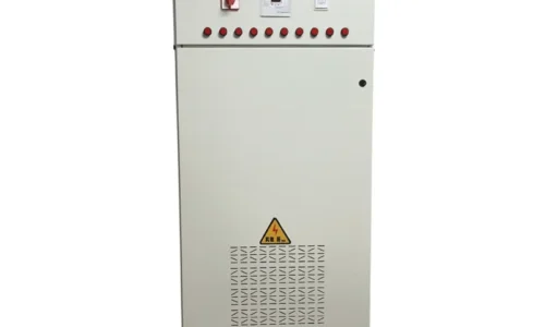
- Fixed capacitor banks providing constant correction
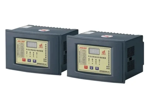
- Automatically switched banks responding to load changes
- Individual motor correction capacitors installed at each load
- Centralized correction at main distribution points
- Distributed correction throughout facility substations
Fixed banks work adequately where loads stay relatively constant. But most facilities experience significant load variation throughout operating shifts. Automatic systems—often called APFC panels—adjust capacitance online to match actual conditions.
Advantages of Capacitor-Based Correction
Capacitors dominate power factor correction for good reasons:
- Lowest capital cost per kVAR of correction
- Simple installation and maintenance
- No moving parts in the capacitors themselves
- Scalable from small to very large applications
- Mature technology with proven reliability
- Available in configurations for various voltage levels
Limitations Worth Considering
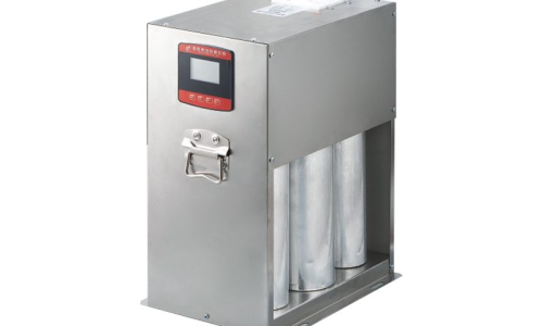
Capacitors aren’t perfect solutions everywhere. They can amplify harmonic distortion in systems with significant non-linear loads. Resonance conditions sometimes develop that cause unexpected problems. And capacitors provide fixed reactive power output—they can’t adjust dynamically to rapid load changes.
Facilities with heavy harmonic content often require detuned configurations that include series reactors. This prevents problematic resonance while still providing correction benefit.
Method Two: Synchronous Condensers for Power Factor Improvement
Understanding Synchronous Condenser Operation
Synchronous condensers are essentially synchronous motors running without mechanical load. They spin at synchronous speed, connected to the grid, but instead of driving equipment, they generate or absorb reactive power based on their excitation level.
Overexcite the field winding, and the machine generates leading reactive power—like a capacitor. Underexcite it, and the machine absorbs reactive power—like an inductor. Adjust excitation continuously, and you get smooth, variable reactive power control across a wide range.
The technology predates solid-state alternatives by decades. Large synchronous condensers have operated at utility substations since the early twentieth century. Some installations from the 1950s still run today.
Where Synchronous Condensers Excel
Certain applications favor this approach:
- Utility substations needing both voltage support and inertia
- Locations requiring both leading and lagging capability
- Systems where harmonic resonance precludes capacitor use
- Critical facilities requiring rotating mass for stability
The inertia contribution deserves mention. Rotating machines store kinetic energy that helps stabilize frequency during disturbances. As conventional generation decreases and inverter-based resources increase, this stored energy becomes increasingly valuable.
Comparing Costs and Complexity
Aspect | Capacitor Banks | Synchronous Condensers |
Capital cost | Lower | Higher |
Operating cost | Minimal | Continuous (losses) |
Maintenance | Periodic inspection | Regular rotating equipment service |
Response speed | Instantaneous (switched) | Seconds to minutes |
Harmonic impact | May cause resonance | Generally neutral |
Space requirement | Compact | Large |
Typical applications | Industrial, commercial | Utility transmission |
For most industrial power factor correction needs, capacitors make more economic sense. Synchronous condensers find their niche in utility applications where their unique characteristics justify higher costs.
Method Three: Phase Advancers for Power Factor Correction
What Phase Advancers Actually Do
Phase advancers target a specific problem—the lagging power factor of wound-rotor induction motors. These machines, common in applications requiring variable speed or high starting torque, draw substantial reactive current during operation.
A phase advancer mounts on the motor shaft and feeds exciting current into the rotor circuit at slip frequency. This effectively provides excitation that the stator would otherwise need to supply from the mains. The motor’s power factor improves without external capacitors or synchronous machines.
Practical Implementation Details
Installation involves several considerations:
- Only applicable to wound-rotor (slip-ring) induction motors
- Requires mechanical connection to motor shaft
- Must be sized appropriately for motor rating
- Needs maintenance as rotating equipment
The technology works well for large wound-rotor motors in continuous operation. Mining applications, cement mills, and similar heavy industry sometimes use phase advancers where their specific characteristics suit the application.
Limited but Useful Applications
Selecting the Right Power Factor Correction Method
Assessment Process
Choosing appropriately requires understanding facility characteristics:
- Measure existing power factor across various operating conditions
- Identify major contributors to poor power factor
- Assess harmonic content and potential resonance risks
- Consider load variability and correction response needs
- Evaluate available space and installation constraints
- Calculate economic payback for different approaches
Hybrid Approaches
Many facilities combine methods. Capacitor banks handle bulk correction economically. Synchronous motors in the process—if any exist—operate slightly overexcited to contribute additional correction. Individual motor capacitors address specific problem loads.
This layered approach often optimizes overall cost while achieving target power factor reliably.
The Economic Case for Power Factor Improvement
Beyond penalty elimination, improved power factor delivers tangible benefits:
- Reduced current lowers cable and transformer losses
- Released capacity defers infrastructure upgrades
- Better voltage improves equipment performance
- Lower demand charges in some utility rate structures
- Extended equipment life from reduced thermal stress
Payback periods vary but commonly fall between one and four years for well-designed installations. The investment continues generating returns for equipment lifetime—typically 15-25 years for capacitor systems.
FAQ
What is considered a good power factor for industrial facilities?
Most utilities consider 0.90 to 0.95 acceptable without penalties. Optimal targets typically fall between 0.95 and 0.98—high enough to avoid charges and maximize benefits without risking overcorrection problems from leading power factor.
Can improving power factor reduce electricity bills significantly?
Yes, particularly for facilities currently paying power factor penalties. Total savings vary but commonly range from 5-15% of electricity costs when combining penalty elimination with reduced demand charges and lower losses.
Do all three methods work for any application?
No. Capacitors suit most industrial and commercial applications. Synchronous condensers fit utility-scale needs requiring inertia and dynamic response. Phase advancers apply only to wound-rotor induction motors. The best method depends on specific facility characteristics and requirements.