Table of Contents
Understanding What a Reactive Power Compensator Actually Does
Electrical systems are rarely as efficient as they appear. Behind the scenes, a significant portion of current flowing through wires doesn’t perform any useful work at all. It simply oscillates back and forth, taking up space in cables and stressing equipment without contributing to actual output.
This problematic energy is reactive power. And a reactive power compensator exists specifically to address it.
In simple terms, these devices balance out the unproductive current that inductive equipment generates. Motors, transformers, and various industrial machines all create reactive power as a byproduct of their operation. Without compensation, this reactive component increases total current flow, causes voltage issues, and triggers penalty charges from utility companies.
The concept sounds technical—and it is, somewhat—but the practical benefits are surprisingly straightforward. Lower bills. Better equipment performance. More available capacity in existing infrastructure.
How a Reactive Power Compensator Works
The Fundamental Operating Principle
Inductive loads produce what engineers call lagging reactive power. The current waveform falls behind the voltage waveform, creating inefficiency. Capacitors, conversely, produce leading reactive power where current leads voltage.
A reactive power compensator typically uses capacitors (or other technologies) to inject leading reactive power into the system. This leading power cancels out the lagging power from inductive loads. The two essentially neutralize each other.
What remains is primarily real power—the useful stuff that actually runs equipment and produces output. Total current decreases even though productive work stays the same.
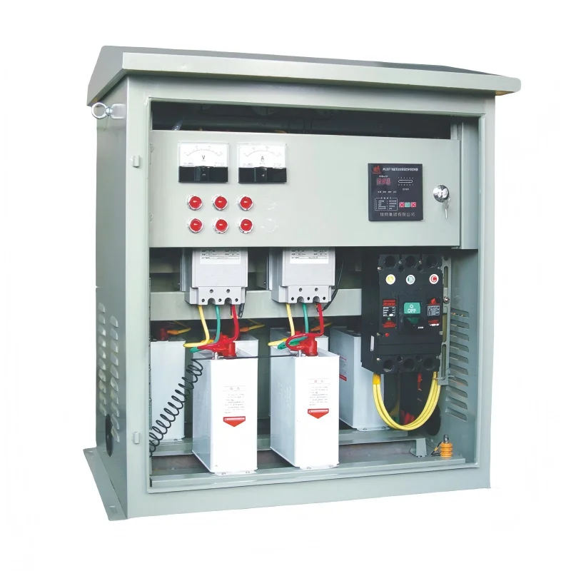
Components Inside Typical Units
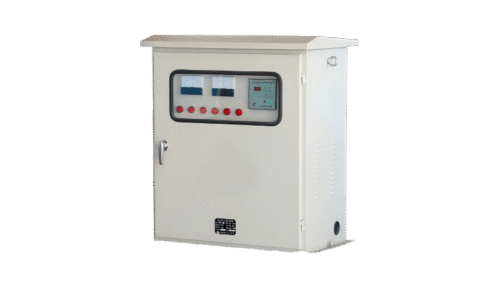
Modern compensator systems contain several integrated elements:
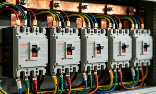
- Capacitor banks arranged in switchable stages
- Contactors or thyristors for connecting capacitor steps
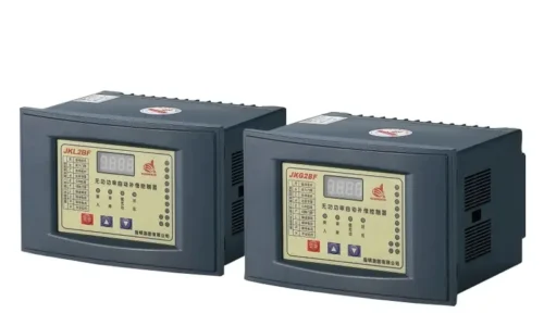
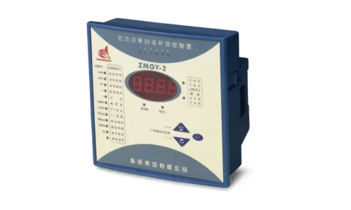
- Power factor controllers with monitoring capabilities
- Protective devices including fuses and breakers
- Discharge resistors for safe shutdown
- Sometimes harmonic filters for distorted environments
The controller constantly monitors electrical parameters and decides which capacitor stages to activate. This happens automatically, usually within seconds of detecting changes in load conditions.
Types of Reactive Power Compensator Systems
Fixed Compensation Units
The simplest approach involves permanently connected capacitors providing constant reactive power. These work adequately when load conditions remain stable throughout operations.
A facility running identical equipment around the clock, for instance, might find fixed compensation perfectly suitable. The predictability makes sizing straightforward and keeps costs down.
The limitation? Real-world loads rarely stay constant. Shift changes, production variations, and equipment cycling all cause fluctuations that fixed systems cannot address.
Automatic Switched Compensators
Variable conditions demand smarter solutions. Automatic reactive power compensator units monitor power factor in real time and switch capacitor stages accordingly.
The sequence typically follows this pattern:
- Controller measures voltage and current continuously
- Calculates current power factor from measurements
- Compares against target setpoint
- Switches capacitor stages in or out as needed
- Waits briefly then reassesses conditions
This cycling maintains correction across varying loads without manual intervention. Most industrial installations use automatic systems for this reason.
Static VAR Compensators
For applications requiring extremely fast response—or dealing with rapidly fluctuating loads like arc furnaces—static VAR compensators offer advantages. These use power electronics (thyristors) to adjust reactive power almost instantaneously.
The technology costs more than traditional switched capacitor banks. But in demanding applications, that premium delivers genuine value through superior performance and equipment protection.
Active Power Filters
When harmonic distortion complicates the picture, active filters provide both compensation and harmonic mitigation simultaneously. These sophisticated units analyze incoming current, identify unwanted components, and generate opposing signals to cancel them out.
Compensator Type | Response Speed | Harmonic Handling | Relative Cost |
Fixed capacitor bank | N/A | Poor | Low |
Automatic switched | Seconds | Poor to moderate | Medium |
Static VAR compensator | Milliseconds | Moderate | High |
Active power filter | Milliseconds | Excellent | Highest |
Benefits of Installing a Reactive Power Compensator
Utility Cost Reduction
Most electricity providers penalize facilities operating below acceptable power factor thresholds—commonly around 0.9 or 0.95. These penalties appear as surcharges on monthly bills and can represent substantial amounts for larger operations.
A properly sized reactive power compensator eliminates these charges essentially overnight. Many facilities report payback periods under three years, sometimes significantly less.
Released System Capacity
Here’s something worth emphasizing. Reactive current consumes capacity in cables, transformers, and switchgear without performing useful work. When compensation reduces this reactive component, that capacity becomes available for real power instead.
Growing facilities often discover they can defer expensive infrastructure upgrades simply by improving power factor. The existing equipment handles increased production because it’s no longer wasting capacity on reactive current.
Improved Voltage Stability
Reactive current flowing through system impedance causes voltage drops. Equipment far from the supply source suffers more than equipment nearby. Motors might run below optimal voltage, affecting performance and efficiency.
Compensation reduces current flow, which reduces voltage drop. The result is more consistent voltage throughout the distribution system.
Extended Equipment Lifespan
Lower current means less heating in conductors and connections. Transformers run cooler. Contact points in switchgear experience less stress. These factors contribute to longer service life and fewer unexpected failures.
The maintenance savings alone can justify compensation investments in some cases.

Essential Safety Checks Before Testing an EV Charging Station
Assessing Current Conditions
Proper sizing requires actual measurements, not estimates. Key data points include:
- Existing power factor under typical load conditions
- Total reactive power demand in kVAR
- Load variation patterns throughout operating cycles
- Presence of harmonic-producing equipment
- Ambient temperature conditions
Undersized systems fail to achieve target correction. Oversized systems waste capital and risk overcorrection problems.
Accounting for Future Changes
Smart planning considers where the facility is headed, not just where it stands today. Expansion plans, new equipment acquisitions, and anticipated load growth all influence optimal compensator sizing.
Modular systems offer flexibility here—additional stages can be added later as needs evolve.
If you want to know more about reactive power compensator, please read Why is reactive power compensation necessary.
FAQ
What happens if a reactive power compensator is oversized?
Overcorrection pushes power factor into leading territory, which can cause voltage rise and potentially damage equipment. Some utilities also penalize leading power factor. Proper sizing and automatic controls prevent this issue.
Can reactive power compensators work in harmonic-rich environments?
Standard capacitor-based compensators can experience problems with harmonics, including resonance and premature failure. Detuned systems or active filters handle harmonic conditions more effectively.
How much maintenance does a reactive power compensator require?
Annual inspections are typically recommended. Technicians check capacitor condition, contact wear, connection tightness, and controller operation. Well-maintained systems commonly last 15 years or longer.