Power transmission and distribution systems face challenges that low voltage installations never encounter. Moving electricity across hundreds of miles, managing reactive power at grid scale, maintaining voltage stability across entire regions—these require specialized equipment.
A high voltage capacitor bank addresses these challenges. Operating at voltage levels from 34.5 kV up to 500 kV or beyond, these installations form critical infrastructure for modern power grids. Without them, electricity simply couldn’t travel efficiently from generating stations to end users.
The functions they serve go well beyond basic power factor correction. Though that remains important, the broader grid-level applications make these systems essential.

Table of Contents
Reactive Power Compensation at Grid Scale
Why Reactive Power Matters
Transmission lines and transformers consume reactive power. Long lines in particular develop significant reactive demands just from their inherent inductance. This reactive power must come from somewhere—either generators (which reduces their capacity for real power) or capacitor banks.
A high voltage capacitor bank installed at substations supplies this reactive power locally. Generators can focus on producing useful energy. System efficiency improves.
Compensation Locations
Strategic placement matters significantly:
- Generating station switchyards
- Transmission substations
- Major load centers
- Critical interconnection points
- Midpoints of long transmission lines
Each location serves slightly different purposes, but all contribute to overall system reactive power balance.
Voltage Regulation and Stability
The Voltage-Reactive Power Relationship
Voltage levels across power systems depend heavily on reactive power flows. Insufficient reactive power causes voltage to sag. Excess reactive power pushes voltage upward. Maintaining proper voltage throughout the grid requires careful management.
A high voltage capacitor bank provides voltage support by supplying reactive power where needed. During heavy load periods when voltage tends to drop, capacitor banks help maintain acceptable levels.
System Stability Implications
Voltage stability affects more than just equipment performance. Severe voltage depression can cascade into widespread blackouts. Major grid disturbances often involve voltage collapse as a contributing factor.
Properly placed capacitor banks enhance system stability margins. They provide reserves of reactive support that help the grid ride through disturbances.
Increasing Transmission Capacity
Benefit | Impact | Result |
Reduced reactive current | Lower line loading | More real power capacity |
Improved voltage profile | Higher transfer limits | Extended reach |
Decreased losses | Less heating | Increased thermal capacity |
Building new transmission lines costs enormously—often billions of dollars—and faces regulatory hurdles that can delay projects for years. Installing a high voltage capacitor bank might achieve similar capacity improvements at a fraction of the cost and time.
Loss Reduction Across Transmission Networks
How Losses Accumulate
Current flowing through transmission lines produces heat. More current means more heat, which in turn leads to greater energy losses. Since reactive current contributes to the total current, reducing reactive power flow helps minimize these losses.
When high voltage power capacitor banks supply reactive power locally—instead of relying on distant generators to deliver it through long transmission lines—several benefits follow:
Less current travels through transmission lines
Resistive losses decrease proportionally
More generated energy reaches end consumers
Fuel consumption at power plants is reduced
Carbon emissions decrease accordingly
Economic and Environmental Impact
Large utilities report loss reductions worth millions of dollars annually after installing transmission-level capacitor banks. The environmental benefits—reduced fuel burn, lower emissions—add further value that’s harder to quantify but increasingly important.
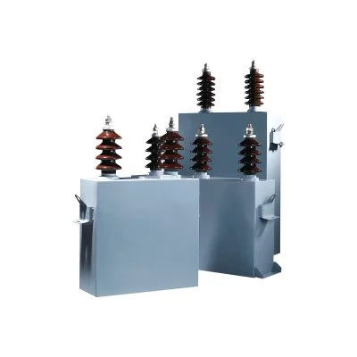
High Voltage Capacitor Bank Components
Typical Elements
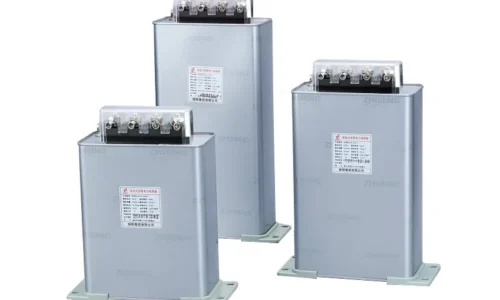
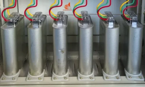
A complete high voltage capacitor bank includes:
- Individual capacitor units (typically 100-300 kVAr each)
- Fusing systems for unit protection
- Steel rack structures for mounting
- Series reactors when detuning is needed
- Disconnect switches for isolation
- Protective relaying systems
- Grounding equipment
- Surge arresters
Configuration Options
Banks can be connected in various arrangements—grounded wye, ungrounded wye, or delta configurations. The choice depends on system requirements, protection philosophy, and utility preferences. Each has advantages for particular applications.
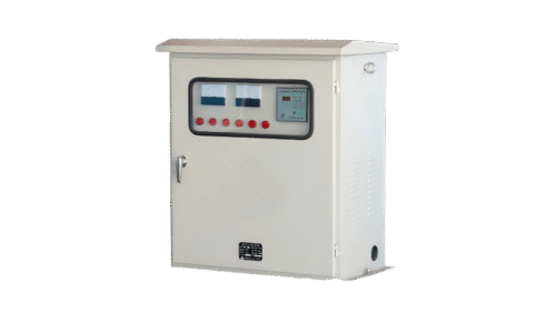
Switching and Control Considerations
Unlike fixed low voltage installations, most transmission capacitor banks get switched based on system conditions.
Time-of-day switching handles predictable load patterns. Voltage-controlled switching responds to actual system conditions. Some modern installations use sophisticated control schemes that coordinate multiple banks across wide areas.
The switching devices themselves must handle significant duties. Circuit breakers rated for capacitor switching differ from standard breakers—they must manage the high transient inrush currents and restrikes that capacitive circuits produce.
FAQ
What voltage levels qualify as high voltage for capacitor banks?
Definitions vary somewhat by region and utility practice. Generally, high voltage capacitor bank installations operate at 34.5 kV and above. Medium voltage typically covers 2.4 kV to 34.5 kV, while low voltage means below 1000 volts. Transmission-class banks often operate at 115 kV, 230 kV, or even higher.
How large are typical high voltage capacitor bank installations?
Transmission-level banks commonly range from 25 MVAr to 300 MVAr or more. A single substation might have multiple banks totaling several hundred MVAr of compensation. The physical size is substantial—large outdoor installations covering considerable yard space.
What happens if a high voltage capacitor bank fails?
Protection systems isolate failed banks quickly to prevent damage spreading. Individual unit failures get cleared by fuses while the rest of the bank continues operating. Complete bank failures cause protection relays to trip the bank offline. System operators then dispatch reactive power from other sources until repairs are completed.