Walk into any industrial facility, and you will hear motors humming, transformers buzzing. That sound is magnetic fields building up and collapsing. Those fields need energy—reactive power. The utility supplies it, but they do not charge you directly. Instead, they penalize you through power factor charges.
Reactive power compensation is how facilities fix that. Put simply, it is generating the reactive power locally so the utility does not have to. The result shows up on the bill. Lower charges. Sometimes significantly lower.
Table of Contents
What Reactive Power Actually Is
Before getting into compensation, understanding what is being compensated helps.
Real Power vs. Reactive Power
Real power does the work. Lights, heaters, motors turning shafts. That is what the meter measures and what the utility bills for.
Reactive power does no work. But motors and transformers need it to create magnetic fields. It circulates in the system, taking up capacity on cables and transformers without contributing to output.
Reactive power compensation provides that circulating current locally. Instead of flowing all the way back through the utility transformer, it moves between the capacitor bank and the inductive load.

Power Factor
Power factor is the ratio between real power and apparent power. A motor running at 0.8 PF means 80% of the current drawn does work. The other 20% just circulates.
Utilities care because low power factor means they have to deliver more current for the same real work. That requires bigger transformers, thicker cables. So they penalize it.
How Reactive Power Compensation Works
The standard solution is capacitors. They generate leading current. Inductive loads draw lagging current. Put them together, and they cancel each other out.
The Basic Setup
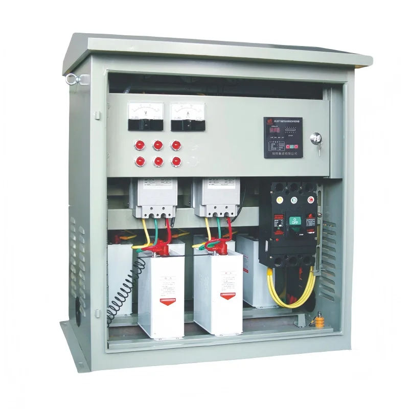
A Reactive Power Compensation system typically has:
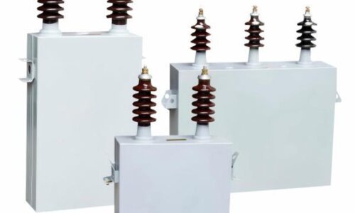
- Capacitor banks that supply the reactive current
- Switching devices (contactors or thyristors) to turn banks on and off
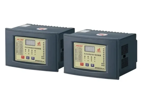
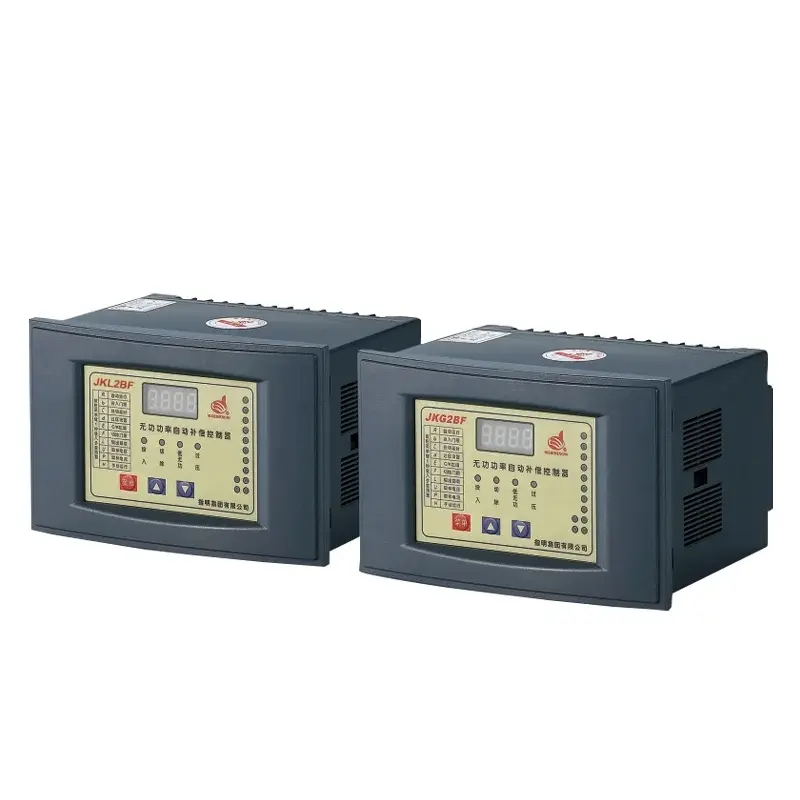
- A controller that monitors the system and decides when to switch
The Reactive Power Compensation Controller watches the power factor. When it drops below the setpoint, it brings in more capacitors. When it goes above, it takes some out.
Why Automatic Control Matters
Fixed capacitor banks work fine for constant loads. But most industrial loads vary. A bank sized for peak load will over-correct during light load. Over-correction creates leading power factor, which utilities also penalize.
Automatic controllers solve this. They bring capacitors in and out as needed, keeping the power factor within a target range—usually 0.95 to 0.98.
Types of Reactive Power Compensation Controllers
Different reactive power compensation applications require different capacitor controllers. The table below summarizes common options.
| Controller Type | Application | Key Feature | Typical Setup |
|---|---|---|---|
| Reactive Power Compensation Controller | General purpose | Monitors PF, switches capacitors | Centralized banks, varying loads |
| Split-phase Capacitor Controller | Unbalanced systems | Individual phase control | 480V panels, single-phase loads |
| Three Phase Capacitor Controller | Balanced systems | Simultaneous three-phase switching | 6kV, 10kV, 35kV substations |
General Purpose Controllers
For most facilities, a standard Reactive Power Compensation controller does the job. It measures current and voltage on the incoming feeder, calculates power factor, and switches capacitor steps accordingly.
These controllers typically handle 6 to 12 capacitor steps. They work well for balanced loads where the power factor on all three phases is roughly the same.
Split-Phase Capacitor Controllers
Some systems have unbalanced loads. Single-phase equipment, LED lighting, office loads—they create imbalance across phases. A standard controller might correct one phase while leaving others under- or over-corrected.
The Split-phase Capacitor Controller addresses this by monitoring and switching each phase individually. It uses three separate measurement inputs and three sets of outputs. That way, each phase gets its own correction.
One electrical contractor mentioned using these in office buildings where tenant loads vary unpredictably. The split-phase approach kept the power factor stable even when individual phases had different loads.
Three Phase Capacitor Controller
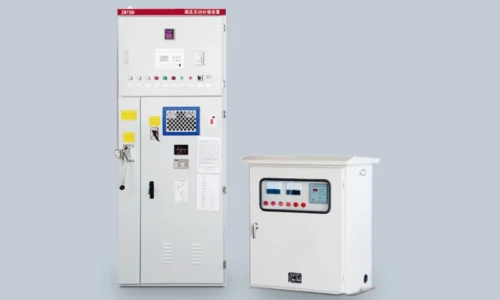
For large, balanced systems—substations, heavy industrial plants—the Three Phase Capacitor Controller is the standard. It measures all three phases but assumes the load is reasonably balanced.
These capacitor controllers often have more steps, higher current ratings, and more sophisticated algorithms for dealing with harmonic distortion. They are built for environments where reliability matters more than per-phase precision.
Installation Considerations for Reactive Power Compensation
Putting in a compensation system is not complicated, but a few things can go wrong if overlooked.
Measurement Point
The controller needs to measure current where it can see the whole load. Usually at the main incoming feeder. Put it downstream of some loads, and those loads will not be compensated.
Current Transformer Placement
Current transformers must be installed with correct polarity. Reverse the Current T transformer, and the controller sees the wrong direction of power flow. It will try to correct in the wrong direction, making things worse instead of better.
Harmonic Content
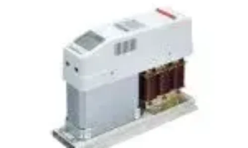
Capacitors and harmonics do not always mix well. If the facility has variable frequency drives or other non-linear loads, standard capacitors can amplify harmonics. In those cases, detuned filters (capacitors with series reactors) are safer.
The controller still works. But the capacitor bank needs to be designed for harmonic conditions.
Common Problems in Reactive Power Compensation Systems
Even with proper design, issues come up.
Hunting
Sometimes a controller cycles capacitors on and off repeatedly. This happens when the setpoint is too tight or the step sizes are too large. The solution is adjusting the setpoint or using smaller step sizes.
Capacitor Failure
Capacitors age. When they fail, the bank loses capacity. The controller tries to compensate but cannot reach the target. Regular thermal imaging or current checks catch failing capacitors before they become a problem.
Wrong Current Transformer Placement
If the Current Transformer is on the wrong side of the capacitor bank, the controller sees the capacitors as part of the load. It keeps adding more, leading to over-correction. The fix is moving the Current Transformer to the utility side.
Conclusion
Reactive power compensation is not complicated, but it does require attention to detail. The right approach balances capacitor sizing, controller selection, and proper installation.
Start with good measurements. Know the load profile—peak, average, and light load. Pick a controller that matches the system: Reactive Power Compensation controllers for general use, Split-phase Capacitor Controller for unbalanced systems, Three Phase Capacitor Controller for balanced, high-power installations.
Size the capacitor steps appropriately. Too few steps and the system cannot fine-tune. Too many and the controller spends all day switching. Check harmonics before selecting capacitors.
Get those basics right, and the system will run for years. The savings show up on the utility bill every month.
FAQ
Can reactive power compensation reduce my electricity bill?
Yes, by improving power factor. Most utilities charge penalties for low power factor. Correcting it to the target range eliminates those charges. The savings often pay for the equipment within one to two years.
What is the difference between a split-phase and a three-phase controller?
A split-phase controller monitors and switches each phase individually. It is used for unbalanced loads where different phases have different power factors. A three-phase controller switches all phases together and works best for balanced loads.
Do I need special capacitors if I have variable frequency drives?
Probably yes. VFDs and other non-linear loads create harmonic currents. Standard capacitors can amplify these harmonics. Detuned filter banks—capacitors with series reactors—are the safer choice in harmonic-rich environments. Your controller still works normally, but the capacitor bank is designed differently.