Power factor correction comes in different flavors. Some systems adjust automatically based on changing conditions. Others—the fixed variety—take a simpler approach. A fixed capacitor bank delivers a constant amount of reactive power compensation, regardless of what the load is doing at any given moment.
The concept is pretty straightforward. Connect a predetermined amount of capacitance to the electrical system, and it stays connected. No fancy controllers, no switching logic, no automatic adjustments. Just steady, reliable compensation.
This simplicity has its place. Not every facility needs sophisticated automatic systems. For applications with consistent, predictable loads, a fixed capacitor bank often makes more sense than more complex alternatives. Cheaper to buy, easier to install, less that can go wrong.
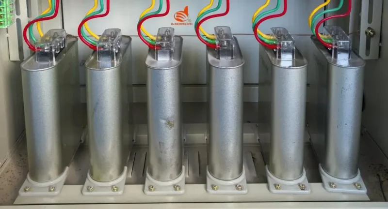
Table of Contents
How a Fixed Capacitor Bank Works
The operating principle couldn’t be simpler, really.
Capacitors store electrical energy in an electric field. When connected to an AC power system, they supply reactive power (measured in kVAr) that offsets the reactive power demanded by inductive loads like motors and transformers.
The Compensation Effect
Inductive loads draw lagging current—current that lags behind voltage. This creates poor power factor. Capacitors draw leading current. When properly sized, the leading current from capacitors cancels out some or all of the lagging current from inductive equipment.
The result? Less reactive current flowing through the electrical system. Better power factor. Lower losses. Reduced utility bills in many cases.
Fixed Versus Stepped Operation
Unlike automatic power factor correction systems that switch capacitor stages on and off, a fixed capacitor bank has only two states: connected or disconnected. Once energized, it provides the same compensation continuously until someone turns it off.
This works well when the reactive power demand stays relatively constant. Problems can arise when loads vary significantly—but more on that later.
Components Inside a Fixed Capacitor Bank
Component | Purpose | Typical Specifications |
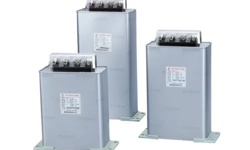
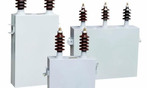
Power Capacitors | Provide reactive power | Rated in kVAr, specific voltage class |
Fuses or MCBs | Overcurrent protection | Sized for capacitor inrush and steady-state current |
Discharge Resistors | Safely discharge stored energy | Reduce voltage to safe levels within minutes |
Contactors or Switches | Connect/disconnect from supply | Rated for capacitive switching duty |
Enclosure | Physical protection | NEMA or IP rated for environment |
Bus Bars | Internal connections | Copper or aluminum, properly sized |
Some installations also include:
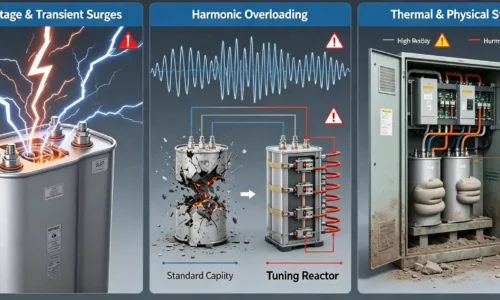
- Surge arresters for transient protection
- Indicating lights showing operational status
- Current transformers for monitoring
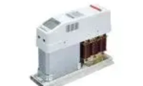
- Detuning reactors if harmonics are present
Where Fixed Capacitor Bank Installations Make Sense
Stable Industrial Loads
Manufacturing processes that run continuously at consistent levels are ideal candidates. A factory running the same motors at the same speeds around the clock doesn’t need automatic adjustment. Fixed compensation handles this perfectly.
Individual Motor Correction
Sometimes LV capacitor banks are installed right at the motor terminals. This provides power factor correction at the source, reducing current through all upstream cables and equipment. Since individual motors typically run at consistent loads, fixed compensation—often delivered by such an LV capacitor bank—works well here.
Transformer Compensation
Power transformers consume reactive power even when lightly loaded. Installing a fixed capacitor bank sized for the transformer’s magnetizing current provides base-level compensation that’s always appropriate.
Advantages of Choosing a Fixed Capacitor Bank
Why go with fixed compensation? Several reasons stand out.
- Lower initial cost compared to automatic systems
- Simpler installation with fewer components
- Reduced maintenance requirements
- No control system to configure or troubleshoot
- Higher reliability due to fewer moving parts
- Longer service life when properly applied
- No controller failures to worry about
There’s something to be said for simplicity. Automatic systems offer more flexibility, true. But that flexibility comes with complexity, and complexity means more potential failure points.
For the right application, a fixed capacitor bank represents the most cost-effective solution. Spending money on automatic features that aren’t needed doesn’t make much sense.
Sizing a Fixed Capacitor Bank Correctly
Getting the size right matters considerably. Too small, and power factor doesn’t improve enough. Too large, and overcorrection problems emerge.
The basic approach involves:
- Measuring existing reactive power demand (kVAr)
- Determining the target power factor
- Calculating required compensation
- Selecting standard capacitor sizes that meet the need
- Allowing some margin for load variation
For fixed installations, it’s generally better to size slightly conservatively. A bit of remaining lagging power factor causes fewer problems than overcorrection.
Installation Considerations
Putting in a fixed capacitor bank requires attention to several factors.
Location matters. The bank should be:
- Near the loads being compensated when possible
- In a well-ventilated area
- Protected from extreme temperatures
- Accessible for inspection and maintenance
- Away from heat sources
Electrical considerations include proper protection sizing, appropriate cable ratings (capacitor circuits often carry more current than expected), and compliance with applicable codes. The switching device must be rated for capacitive duty—regular contactors or breakers may not handle the inrush current properly.
FAQ
Can a fixed capacitor bank be used with variable frequency drives?
Using fixed capacitors with VFDs requires caution. VFDs generate harmonic currents that can damage standard capacitors and cause resonance problems. If VFDs are present, detuned reactors should be added to protect the capacitor bank, or the bank should be installed upstream of VFD inputs.
What happens if a fixed capacitor bank is oversized?
Oversizing leads to overcorrection—a leading power factor condition. This can cause elevated voltage levels throughout the facility, potential damage to sensitive equipment, and penalties from some utilities. Severe overcorrection might even trigger protective relays.
How long does a fixed capacitor bank typically last?
Properly applied fixed capacitor banks commonly last 12 to 20 years. Lifespan depends heavily on operating conditions—voltage stress, harmonic exposure, temperature, and switching frequency all affect longevity. Quality of the original equipment matters too.