Table of Contents
What Is Split Phase Low-Voltage Shunt Power Capacitor?
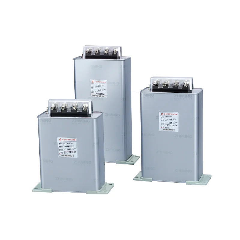
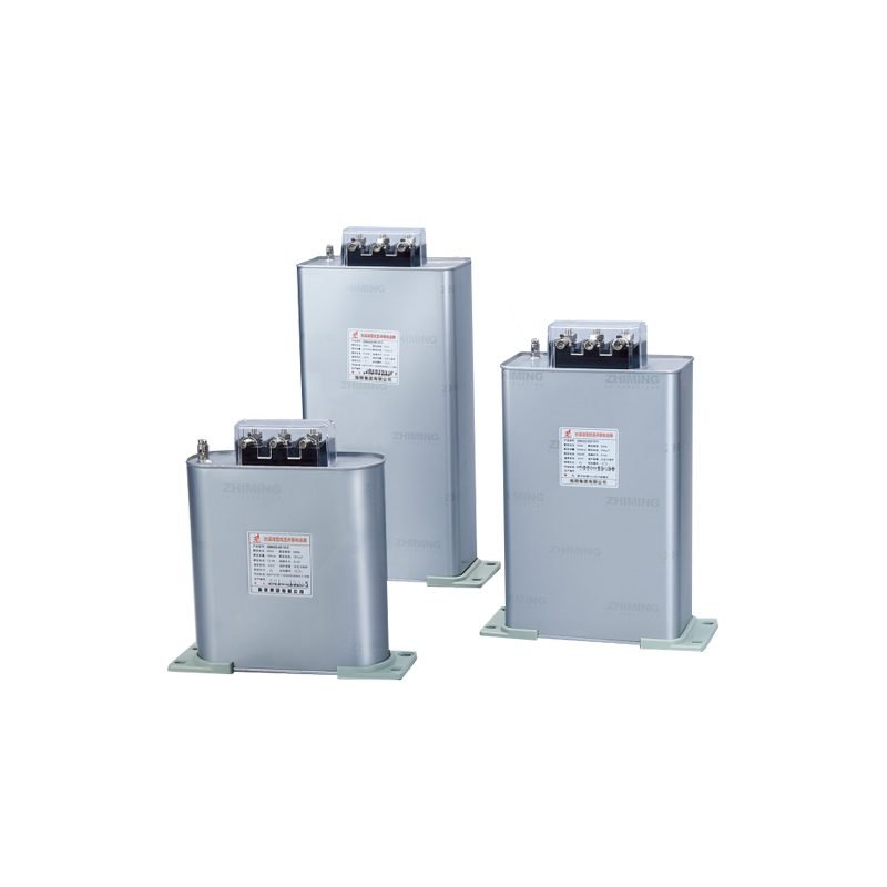
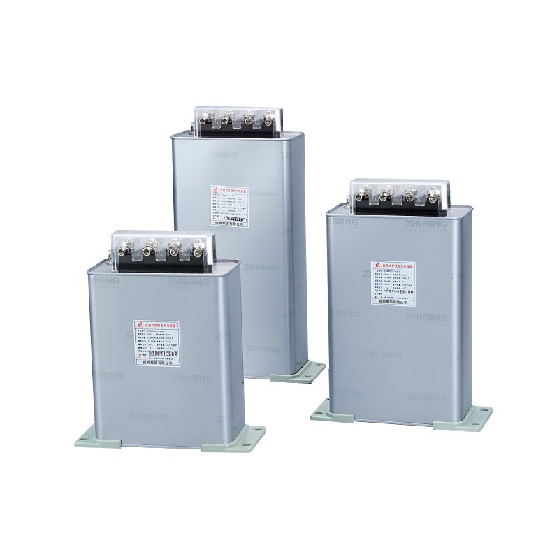
ZHIMING brand of Power reactive compensate technology develop, for three phase unbalance load, you can adapt three phase input cut capacitor way, sub compensate reactive power, so it can make the compensate accuracy is high, saving electric impression is best, so our company develop split phase low-voltage shunt power capacitor, his cover setting neuter lead to terminal block, it can convenient make power capacitor sub cut and input. This product instruction characteristic mainly about technology data.
Working Conditions of the Split Phase Low-Voltage Shunt Power Capacitor
- Altitude level: No more than 2000m.
- Temperature type: it will not be more than 50℃the average temperature is not more than 40℃within 24 hours, the yearly average of temperature is not more than 30℃.
- Power controller type: Must have input lock and repu lock time function after power cut-off.
- Voltage confirmation: Input voltage reduced to 10% of rated voltage before re-energizing.
- Power controller type: Must have input lock and repu lock time function after power cut-off.
- Alternative solution: Install rapid discharge equipment if using standard power controller.
- Discharge equipment requirement: Not limited to same power factor input or chip switch configuration.
Product Parameters
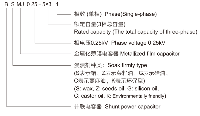
| Model | ||||||||
|---|---|---|---|---|---|---|---|---|
| BSMJ、BCMJ、BZMJ | Rated line voltage(KV) | Rated phase voltage(KV) | Three phase capacty(Kvar) | Rated Capacity(μF) | Rated Current (A) | H(mm) | Outgoing terminal | Drawing No. |
| 0.23-1×3-1 | 0.4 | 0.23 | 3 | 180.6 | 4.3×3 | 105 | M6 | 1 |
| 0.23-1.67×3-1 | 0.4 | 0.23 | 5 | 301.0 | 7.2×3 | 125 | M6 | 1 |
| 0.23-2×3-1 | 0.4 | 0.23 | 6 | 361.2 | 8.7×3 | 130 | M6 | 1 |
| 0.23-2.5×3-1 | 0.4 | 0.23 | 7.5 | 451.5 | 10.9×3 | 160 | M6 | 1 |
| 0.23-3.33×3-1 | 0.4 | 0.23 | 10 | 602.0 | 14.5×3 | 210 | M6 | 2 |
| 0.23-4×3-1 | 0.4 | 0.23 | 12 | 722.0 | 17.4×3 | 210 | M6 | 2 |
| 0.23-5×3-1 | 0.4 | 0.23 | 15 | 903.0 | 21.7×3 | 210 | M6 | 2 |
| 0.23-6.67×3-1 | 0.4 | 0.23 | 20 | 1204.0 | 29.0×3 | 260 | M8 | 2 |
| 0.23-8.33×3-1 | 0.4 | 0.23 | 25 | 1505.0 | 36.2×3 | 270 | M8 | 4 |
| 0.25-1×3-1 | 0.43 | 0.25 | 3 | 152.8 | 4.0×3 | 105 | M6 | 1 |
| 0.25-1.67×3-1 | 0.43 | 0.25 | 5 | 254.8 | 6.7×3 | 125 | M6 | 1 |
| 0.25-2×3-1 | 0.43 | 0.25 | 6 | 305.7 | 8.0×3 | 125 | M6 | 1 |
| 0.25-2.5×3-1 | 0.43 | 0.25 | 7.5 | 382.1 | 10.0×3 | 180 | M6 | 1 |
| 0.25-2.67×3-1 | 0.43 | 0.25 | 8 | 407.6 | 10.7×3 | 180 | M6 | 1 |
| 0.25-3.33×3-1 | 0.43 | 0.25 | 10 | 509.5 | 13.3×3 | 180 | M6 | 1 |
| 0.25-4×3-1 | 0.43 | 0.25 | 12 | 611.5 | 16.0×3 | 210 | M6 | 1 |
| 0.25-5×3-1 | 0.43 | 0.25 | 15 | 764.3 | 20.0×3 | 210 | M6 | 2 |
| 0.25-5.33×3-1 | 0.43 | 0.25 | 16 | 815.3 | 21.3×3 | 210 | M6 | 2 |
| 0.25-6.67×3-1 | 0.43 | 0.25 | 20 | 1019.0 | 26.7×3 | 210 | M6 | 2 |
| 0.25-8.33×3-1 | 0.43 | 0.25 | 25 | 1273.9 | 33.3×3 | 260 | M8 | 2 |
| 0.25-10×3-1 | 0.43 | 0.25 | 30 | 1528.7 | 40.0×3 | 270 | M8 | 4 |
| 0.28-3.33×3-1 | 0.43 | 0.28 | 10 | 406.0 | 11.9×3 | 160 | M6 | 1 |
| 0.28-4×3-1 | 0.43 | 0.28 | 12 | 488.0 | 14.3×3 | 210 | M6 | 2 |
| 0.28-5×3-1 | 0.43 | 0.28 | 15 | 609.0 | 17.9×3 | 210 | M6 | 2 |
| 0.28-6.67×3-1 | 0.43 | 0.28 | 20 | 812.0 | 23.8×3 | 210 | M6 | 2 |
| 0.28-8.33×3-1 | 0.43 | 0.28 | 25 | 1016.0 | 29.8×3 | 210 | M6 | 2 |
| 0.28-10×3-1 | 0.43 | 0.28 | 30 | 1219.0 | 35.7×3 | 260 | M6 | 2 |
| 0.45-9-6 | 0.45 | 0.45 | 9 | 141.0 | 6.67 | 120 | M6 | 2 |
| 0.45-21-6 | 0.45 | 0.45 | 21 | 329.7 | 15.5 | 160 | M6 | 2 |
Main Technical Data of the Split Phase Low-Voltage Shunt Power Capacitor
- Rated voltage: 230VAC, 250VAC, 400VAC, 415VAC, 450VAC, 525VAC.
- Rated capacity: 1~100kvar
- Rated frequency: 50Hz or 60Hz
- Capacity tolerance: -5~+10%
- Loss Angle Tangent(Power Frequency Rated Voltage): tgδ≤0.01 at 20°C
- Anti-voltage: between two poles 2.15 times rated voltage is 10s, between two poles 3kV, please choose the highest value 10s, there is no permissibility puncture and Flash over.
- Max permit over voltage: 1.1times rated voltage, the high permit over voltage is not more than 8 hours within 24 hours; 1.15 times rated voltage, it is not more than 30 minutes within 24 hours; 1.2 times rated voltage, it is not more than 5 minutes; 1.3 times rated voltage, it is not more than 1 minute.
- Max permit over current: it is permitted that the overcurrent is not more than 1.3 times the rated current. Interim overcurrent, it should consider overvoltage, capacity positive tolerance, and harmonic effect. Interim over current is not more than 1.43 times rated current.
- Discharge property: the left voltage will reduce from √2 Un to below 50V within 3 minutes when the power is cut off.
Why Choose ZHIMING's Split Phase Low-Voltage Shunt Power Capacitor?
Designed for Three Phase Unbalance Load
ZHIMING's low-voltage shunt power capacitor handle unbalanced load conditions effectively. The split phase compensation approach addresses real-world power systems where loads rarely distribute evenly across all three phases.
Higher Compensation Accuracy
The sub compensate reactive power method delivers precise power factor correction. Each phase gets individual attention rather than treating all three phases as a single unit, resulting in more accurate compensation results.
Better Energy Saving Performance
Split phase input and cut capacitor technology maximizes energy efficiency. Users typically notice improved electricity savings compared to conventional three phase compensation methods in facilities with unbalanced loads.
Convenient Terminal Block Design
The neutral lead terminal block configuration simplifies installation and maintenance. Technicians can easily connect and disconnect low-voltage shunt power capacitors without complicated wiring procedures.
International Standard Compliance
All products meet IEC 60831-2014 requirements. This ensures reliable performance, safety, and compatibility with global power system specifications and quality expectations.
FAQ
What is split phase compensation technology?
Split phase compensation technology allows each phase to be individually controlled for reactive power correction. Instead of treating all three phases as one unit, this approach cuts and inputs capacitors separately per phase, achieving higher compensation accuracy for unbalanced load conditions.
What standard does ZHIMING's low-voltage shunt power capacitor comply with?
ZHIMING’s split phase low-voltage shunt power capacitor complies with IEC 60831-2014 international standard. This certification ensures the product meets global safety requirements, performance specifications, and quality expectations for power factor correction equipment.
What makes the terminal block design convenient?
The low-voltage shunt power capacitor features a neutral lead connected to a terminal block configuration. This design allows technicians to easily perform sub cut and input operations for each phase. Installation and maintenance become simpler without requiring complicated wiring procedures.
What applications benefit from split phase low-voltage shunt power capacitors?
Facilities with unbalanced three phase loads benefit most from this technology. Common applications include manufacturing plants, commercial buildings, and industrial facilities where load distribution varies significantly between phases throughout daily operations.