Power factor is one of those electrical concepts that sounds more complicated than it actually is. At its core, it’s about how efficiently electrical power is being used. When the power factor is low, a lot of current is flowing through the system without doing any real work — just bouncing back and forth between the source and the load.
That’s where power factor correction comes in. It’s not magic, but the way it works is pretty clever. By adding the right equipment in the right places, reactive power can be supplied locally instead of being drawn from the utility. The result? Lower current, reduced losses, and often a smaller electricity bill.
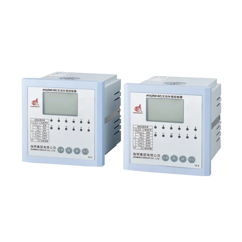
Table of Contents
The Basic Principle Behind Power Factor Correction
To understand how power factor correction works, it helps to think about what’s happening in an electrical system with inductive loads. Motors, transformers, and similar equipment need two types of power:
Active power (measured in kW) — does the actual work
Reactive power (measured in kVAR) — creates magnetic fields but doesn’t perform useful work
The power factor is essentially the ratio of active power to total apparent power. When it’s low, the system is drawing more current than necessary to deliver the same amount of useful work.
Correction works by introducing capacitive reactive power to offset the inductive reactive power. Capacitors and inductors have opposite effects on the phase relationship between voltage and current. When balanced properly, they cancel each other out, bringing the power factor closer to unity.
How Power Factor Correction Equipment Functions
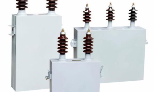
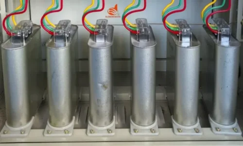
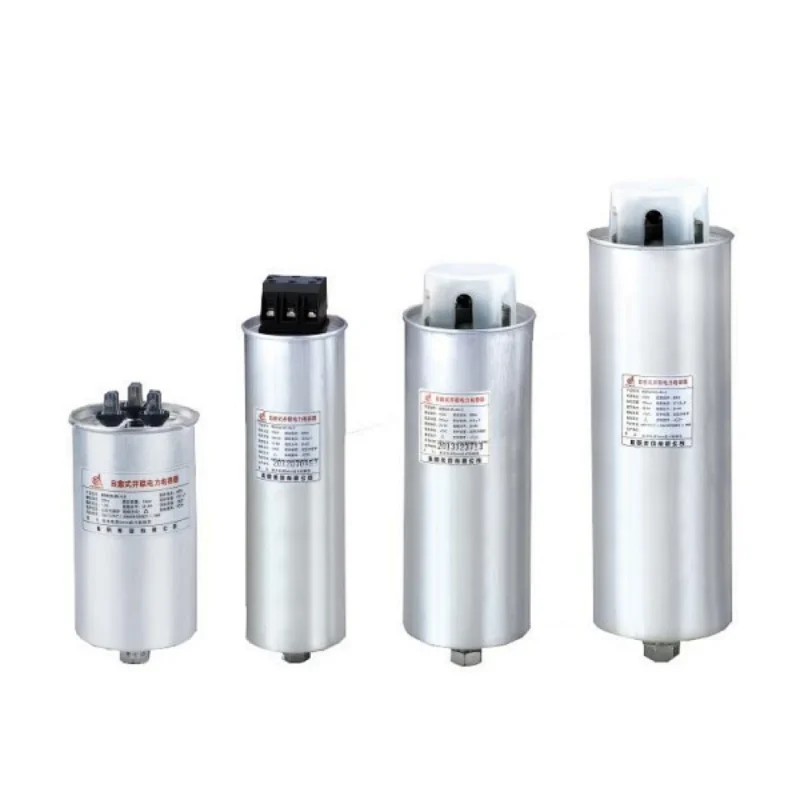
The most common approach involves capacitor banks. These are connected in parallel with the load, either at the main distribution board or closer to individual pieces of equipment.
The Role of Capacitors
Capacitors store and release electrical energy in a way that’s opposite to inductors. While an inductive load causes current to lag behind voltage, a capacitor causes current to lead. By introducing capacitive reactance into the system, the lagging current from inductive loads gets compensated.
It’s a bit like balancing a seesaw. Too much inductive load tips it one way; adding capacitance tips it back toward equilibrium.
Fixed Versus Automatic Correction
Fixed capacitor banks provide a constant amount of reactive power compensation. They work fine when the load is steady, but they don’t adjust if demand changes throughout the day.
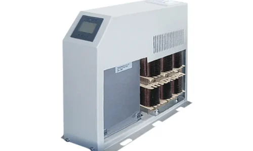
Automatic power factor correction panels solve this by switching capacitor stages on and off based on real-time measurements. A controller monitors the power factor continuously and engages or disengages capacitor steps as needed. This keeps the correction matched to the actual load, avoiding both under-correction and over-correction.
Step-by-Step: How Power Factor Correction Works in Practice
Here’s what happens when power factor correction is applied to a typical industrial facility:
The system initially operates with a low power factor (say, 0.75) due to inductive loads like motors
Capacitor banks are installed at the main switchboard or distribution panels
The capacitors supply reactive power locally, reducing the amount drawn from the utility
Total current flowing through the supply cables decreases
Power factor improves (typically to 0.95 or higher)
Voltage drop across the distribution system is reduced
Losses in cables and transformers decrease
The utility meter still records the same active power consumption (the actual work being done hasn’t changed), but the reactive power demand drops significantly. In regions where utilities charge for reactive power or penalize low power factor, this translates directly into cost savings.
The Physics of Reactive Power Compensation
Getting a bit more technical, the relationship between active power (P), reactive power (Q), and apparent power (S) forms what’s called the power triangle. The power factor is the cosine of the angle between active and apparent power.
When capacitors are added:
The inductive reactive power (QL) from the load remains the same
Capacitive reactive power (QC) is introduced
The net reactive power becomes QL – QC
The apparent power decreases
The power factor angle reduces, improving the cosine value
This is why power factor correction doesn’t reduce the actual energy consumed by the equipment — it reduces the wasted energy circulating in the distribution system.
Practical Considerations in How Power Factor Correction Works
Harmonic Distortion
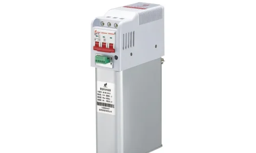
Modern facilities often have variable frequency drives, LED lighting, and other non-linear loads that generate harmonics. Standard capacitors can amplify these harmonics or even create resonance conditions. That’s why detuned reactors are often added in series with capacitors — they shift the resonant frequency away from problematic harmonics.
Switching Transients
When capacitor banks are energized, there’s a brief inrush current. In automatic systems where stages switch frequently, this can cause voltage transients if not properly managed. Most APFC controllers include delay timers and soft-start features to minimize these effects. If you want to know more about power factor correction, please read How to make power factor correction.
FAQ
Does power factor correction reduce the electricity bill?
It can, but not always in the way people expect. Power factor correction doesn’t reduce the active energy consumption (kWh) — the equipment still uses the same amount of power to do its work. However, it reduces reactive power demand, which many utilities charge for separately. It also lowers demand charges in some rate structures and eliminates power factor penalties where they apply.
Can power factor correction improve voltage levels?
Yes, indirectly. By reducing the total current flowing through the distribution system, power factor correction reduces voltage drop across cables and transformers. This often results in slightly higher and more stable voltage at the load end, which can improve equipment performance and efficiency.
How quickly does power factor correction respond to load changes?
It depends on the type of system. Fixed capacitor banks don’t respond at all — they provide constant compensation. Automatic systems with contactors typically respond within a few seconds. Thyristor-switched or active systems can respond in milliseconds, making them suitable for rapidly changing loads.