Table of Contents
Understanding Power Factor and Why It Matters
Power factor represents the relationship between real power and apparent power in an electrical system. When equipment draws more current than necessary to perform actual work, the power factor drops—and that’s when problems start showing up on utility bills.
Most industrial facilities operate somewhere between 0.7 and 0.85 power factor, which honestly isn’t great. Utility companies often penalize customers who fall below 0.9 or 0.95, depending on the region. The charges can add up surprisingly fast, especially for operations running heavy inductive loads like motors, transformers, and fluorescent lighting.
A low power factor essentially means the electrical system works harder than it should. More current flows through wires, equipment runs hotter, and the infrastructure ages faster than expected.
Common Causes of Poor Power Factor
Before jumping into correction methods, identifying what’s dragging down the power factor makes sense. The usual suspects include:
Induction motors running at partial load
Welding machines and arc furnaces
Older fluorescent lighting systems with magnetic ballasts
Variable frequency drives (certain types)
Transformers operating below capacity
Induction motors deserve special attention here. They’re everywhere in industrial settings, and when they run underloaded—say, a 100 HP motor doing 40 HP worth of work—the power factor suffers considerably.
Methods to Correct Power Factor
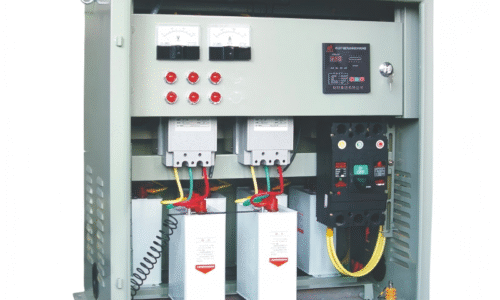
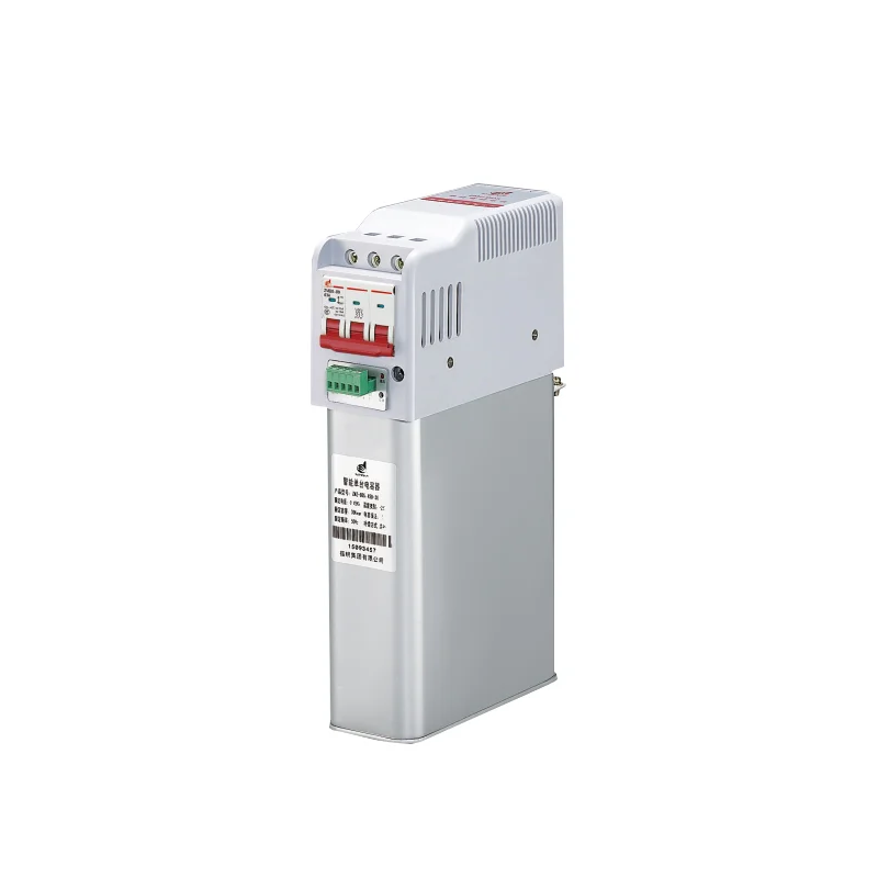
Installing Capacitor Banks
Capacitors remain the most common and cost-effective solution for power factor correction. They supply reactive power locally, reducing the amount drawn from the utility.
There are basically three approaches to capacitor installation:
Individual correction at each motor or load
Group correction for clusters of equipment
Centralized correction at the main distribution panel
Each approach has trade-offs. Individual correction provides the best results but costs more upfront. Centralized systems are cheaper to install but don’t address losses within the facility’s internal wiring.
Synchronous Condensers
For larger facilities with significant reactive power demands, synchronous condensers offer another path. These are essentially synchronous motors running without mechanical load, adjusted to produce leading reactive power.
They’re not as popular as capacitors due to higher maintenance requirements and initial cost. Still, some heavy industrial operations find them worthwhile, particularly where dynamic compensation is needed.
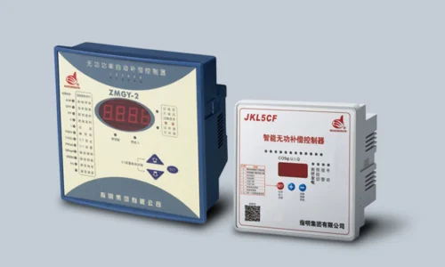
Automatic Power Factor Controllers
Modern correction systems often incorporate automatic controllers that switch capacitor banks on and off based on real-time demand. This prevents overcorrection—which can actually cause problems like voltage rise and harmonic resonance.
Comparing Power Factor Correction Methods
Method | Initial Cost | Maintenance | Best Application | Response Time | |
Fixed Capacitors | Low | Minimal | Steady loads | Instant | |
Automatic Capacitor Banks | Medium | Low | Variable loads | Seconds | |
Synchronous Condensers | High | Moderate to High | Large industrial plants | Continuous | |
Active Filters | High | Low | Harmonic-rich environments | Milliseconds |
Steps to Implement Power Factor Correction
Getting the correction right involves more than just buying capacitors and hooking them up. A reasonable process looks something like this:
Conduct a power quality audit to measure existing power factor across different operating conditions
Identify the primary sources of reactive power consumption
Calculate the required kVAR capacity for target power factor (usually 0.95 or higher)
Select appropriate correction equipment based on load characteristics
Determine installation location—centralized, group, or individual
Install and commission the system with proper protection devices
Monitor results and adjust as needed
Skipping the audit phase tends to result in either undersized or oversized systems. Neither outcome is ideal.
Safety and Maintenance Considerations
Capacitors store energy even after disconnection, which creates obvious hazards during maintenance. Proper discharge procedures and lockout/tagout protocols aren’t optional.
Regular inspections should check for:
Swelling or leaking capacitor cans
Loose connections generating heat
Proper operation of switching contactors
Harmonic distortion levels (capacitors can amplify harmonics if not properly designed)
If you want to know more about power factor device, please read What is a power factor correction device.
FAQ
What is a good power factor target for industrial facilities?
Most facilities aim for 0.95 or higher to avoid utility penalties and maximize efficiency. Some regions require 0.9 as the minimum before surcharges apply.
Can power factor correction damage equipment?
Improperly designed systems can cause issues, particularly harmonic resonance with capacitors. Working with qualified engineers and using detuned reactors in harmonic-rich environments prevents most problems.
How long does it take to see return on investment?
Payback periods typically range from six months to three years, depending on current penalty charges, electricity rates, and system size. Facilities with significant penalties often recover costs within the first year.