A current transformer is one of those devices that rarely gets attention when everything is working, and then suddenly becomes very important the moment readings drift, a relay trips unexpectedly, or a meter starts looking suspicious. In practice, many CT problems do not begin with a dramatic failure. They usually start quietly: a loose terminal, a burden that is a little too high, a secondary that was left open, or moisture that slowly degrades insulation. That is why on-site testing matters so much. It catches small issues before they turn into measurement errors, nuisance alarms, or protection failures.
This guide walks through the field checks that tend to matter most, along with a practical troubleshooting approach for a current transformer in metering or protection service. It also explains when a CT can still be saved and when replacement is the more sensible choice.
Table of Contents
Why On-Site Testing Matters
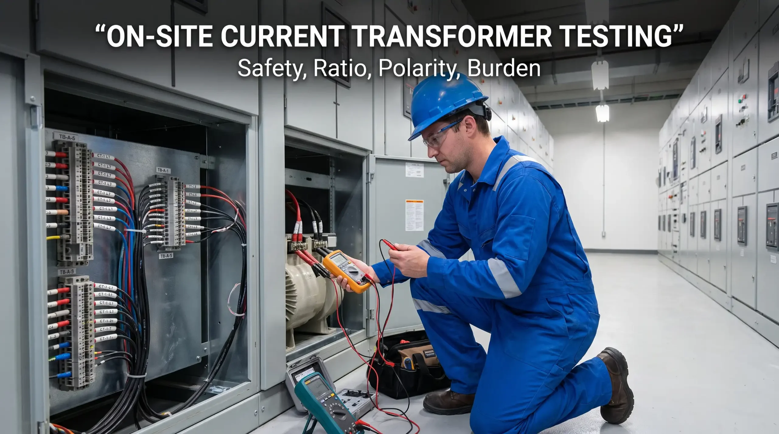
In a controlled lab, a current transformer can be tested under ideal conditions. On site, the picture is different. There may be electrical noise, limited shutdown windows, incomplete drawings, and old wiring that has been modified more than once. That is often where the real problems show up.
A CT is used to step primary current down to a safe, measurable secondary value, usually 1A or 5A. If it is inaccurate, everything connected to it becomes unreliable: meters, relays, protective trip logic, and power quality systems. Even a small error can be expensive in a large installation.
The field experience behind most CT troubleshooting is fairly consistent:
– Many faults are not inside the core itself
– Wiring and termination issues are very common
– Burden mismatch can distort results
– Polarity mistakes can make healthy equipment appear defective
– Saturation can look like failure if the load is not understood correctly
For broader standards context, the IEEE guidance in IEEE C57.13 and the IEC framework in IEC 61869 remain the main references for instrument transformer performance and testing expectations.
Current Transformer Basics Before Testing
Before touching test leads, it helps to be clear on what is being checked.
What a CT actually does
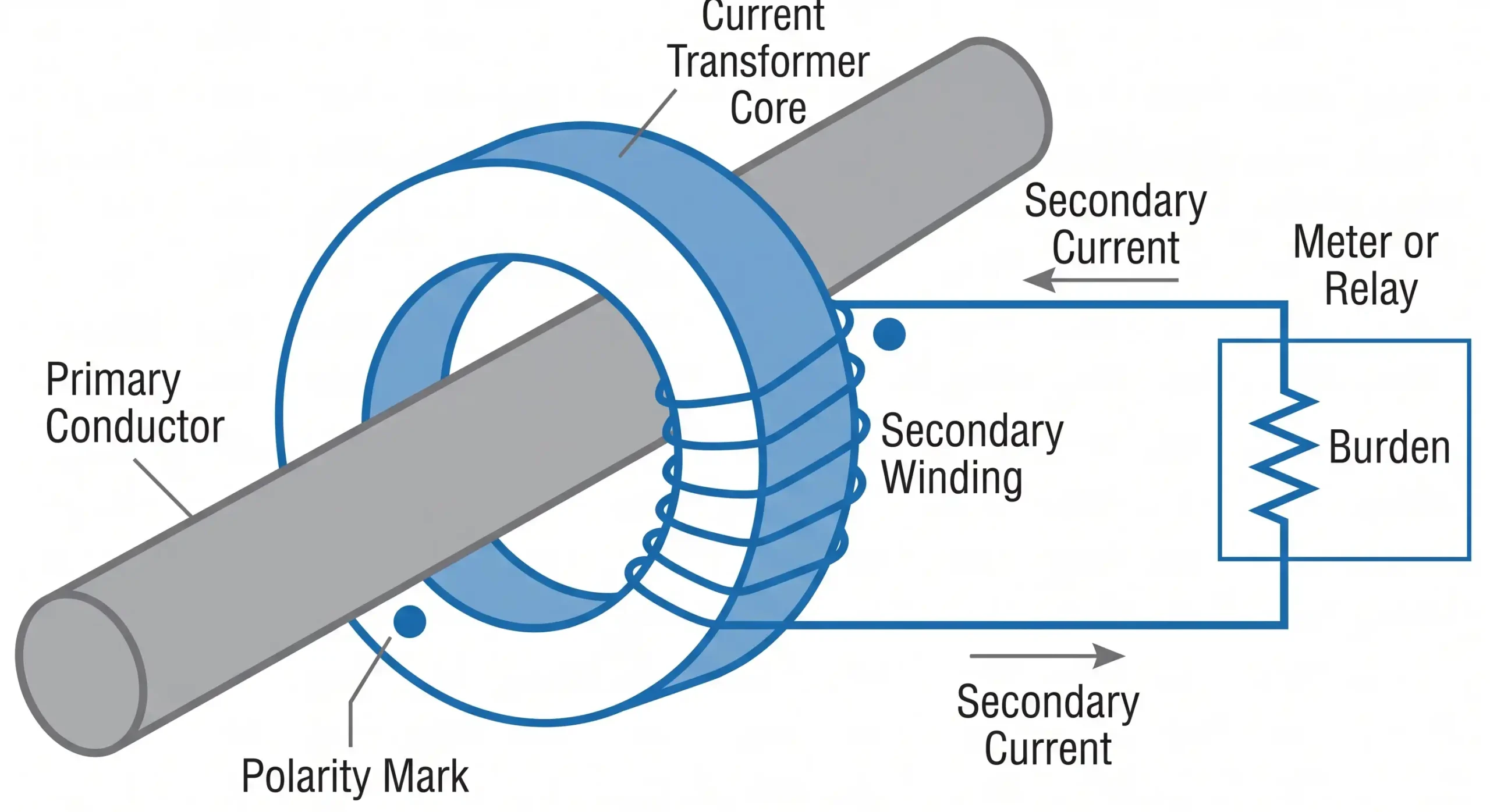
A current transformer reproduces primary current on its secondary side at a reduced ratio. For example, a 600/5 CT produces 5A secondary current when 600A flows in the primary, at least ideally and within its accuracy range.
That ratio can be affected by:
– burden
– magnetic saturation
– wiring resistance
– connection errors
– physical damage
Metering CTs vs protection CTs
Metering CTs are designed for accuracy in normal operating ranges. Protection CTs, on the other hand, need to remain reliable during faults, when current can rise sharply. This difference matters because a CT that seems fine for energy metering may still perform poorly for relay protection.
A low voltage current transformer is often selected for switchboards and compact panels where accurate measurement is needed at lower system voltages. By contrast, higher-energy environments may require a different design approach.
Secondary rating, burden, and polarity
Three terms come up constantly during troubleshooting:
– Secondary rating: usually 1A or 5A
– Burden: the total load connected to the CT secondary circuit
– Polarity: the directional relationship between primary and secondary
If any of these are misunderstood, the test results can look confusing fast.
Safety First: What Must Be Done Before Any Test
This part is not optional. A current transformer secondary should never be left open while the primary is energized. The CT can generate dangerous voltage, and in the field, that risk is taken seriously for good reason.
Before testing:
1. Review the one-line diagram and panel drawings.
2. Confirm whether the CT is used for metering, protection, or both.
3. De-energize and isolate the circuit where possible.
4. Short the CT secondary before disconnecting any leads.
5. Verify absence of voltage using proper procedures.
6. Use the correct PPE and follow site rules.
A good habit in field work is to assume documentation may be incomplete until verified.
Tools Commonly Used On Site
The exact toolkit depends on the installation, but these are common.
| Tool | Purpose | What It Helps Detect |
|---|---|---|
| Multimeter | Checks continuity, resistance, and basic voltage | Open circuits, loose wiring, abnormal resistance |
| Insulation resistance tester | Measures insulation quality | Moisture ingress, degraded winding insulation |
| CT analyzer | Tests ratio, polarity, excitation, and more | Core degradation, ratio error, knee point issues |
| Burden tester | Evaluates connected load | Excessive secondary burden |
| Clamp meter | Confirms real operating current | Load conditions, current imbalance |
| Primary injection set | Applies known current for performance checks | Accuracy and response under realistic loading |
For many technicians, a clamp meter and multimeter provide the first clues, while a CT analyzer is used for deeper verification when the asset is critical.
A Current Transformer used in metering cabinets often can be checked with a simpler field toolkit first, then verified more thoroughly if the readings still look questionable.
Step-by-Step: How to Test a Current Transformer On-Site
A methodical sequence usually gives the clearest result.
CT on-site testing steps
1) Start with a visual inspection
This sounds basic, but it often reveals the answer faster than a test set.
Check for:
– burnt terminals
– cracked insulation
– corrosion
– loose terminal screws
– water ingress
– damaged secondary wires
– evidence of overheating
If the CT is mounted in a dusty or humid area, surface contamination can also mislead later insulation readings.
2) Verify the wiring against the drawing
It is surprising how often the issue is not the CT itself. A reversed pair, a swapped terminal, or a misidentified cable can create misleading readings. Compare the actual installation with the schematic, terminal schedule, and phase labeling.
3) Check secondary continuity
With the circuit safely isolated, check the secondary loop for continuity. An open secondary circuit is a major warning sign.
Look for:
– infinite resistance
– intermittent contact
– poor terminal grip
– broken conductors inside insulation
A simple continuity issue can cause measurement failure or relay misbehavior.
4) Confirm grounding and terminal integrity
Secondary CT circuits are normally grounded at one point. Too many grounds can create unwanted circulating currents; no ground at all can create unsafe conditions and noise problems.
Check:
– single-point grounding
– tight terminal lugs
– clean contact surfaces
– proper shield termination if used
5) Perform a ratio test
This is one of the most important checks for a current transformer. Ratio testing confirms whether the CT output matches the rated transformation under known current.
If the ratio is off significantly, possible causes include:
– shorted turns
– incorrect wiring
– wrong CT nameplate selection
– core damage
– saturation during the test setup
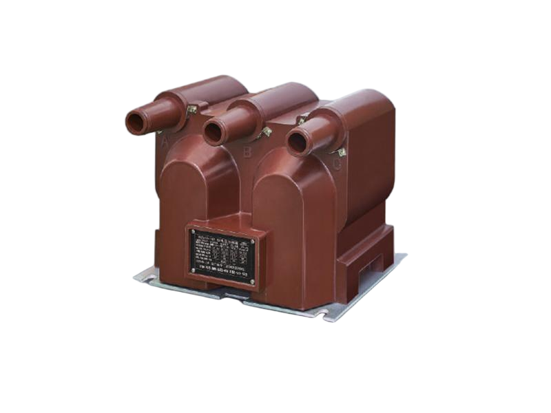
A high voltage current transformer used in substation or switchyard environments may require a more careful ratio and insulation verification process because the installation conditions are typically more demanding.
6) Check polarity
Polarity errors can make healthy equipment seem faulty. In metering circuits, the reading may be reversed or unstable. In protection circuits, polarity problems can interfere with directional logic or differential schemes.
When the polarity is wrong:
– power may appear negative
– phase relationships become confusing
– protection relay logic may fail to coordinate correctly
7) Measure insulation resistance
Insulation testing helps identify winding degradation or contamination. Results should be interpreted against site standards and equipment rating, but low or unstable readings usually deserve attention.
Common reasons for poor insulation results:
– moisture
– dust and conductive contamination
– damaged insulation
– thermal aging
– internal tracking
8) Evaluate burden
Burden is often overlooked, yet it is one of the most common causes of poor accuracy. If the connected load is too high, the CT may not maintain its intended performance.
Typical burden-related issues include:
– long cable runs
– too many devices on one CT secondary
– undersized conductors
– loose terminals adding resistance
A CT that is perfectly healthy can still deliver poor results if the burden is excessive.
9) Observe performance under operating conditions
When possible, compare secondary current against expected primary load. This provides a practical sanity check. If the primary is known and the ratio is known, the secondary should make sense.
That said, on-site operating measurements are only useful when the system state is understood. A partial load, unbalanced phases, or transient conditions can all distort the picture.
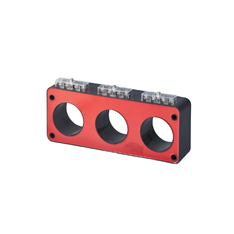
For residual and ground-fault style checks, a Zero Sequence Current Transformer may be used instead of a standard phase CT, especially where leakage current or earth-fault protection needs to be detected reliably.
How to Interpret Common Symptoms of Current Transformer
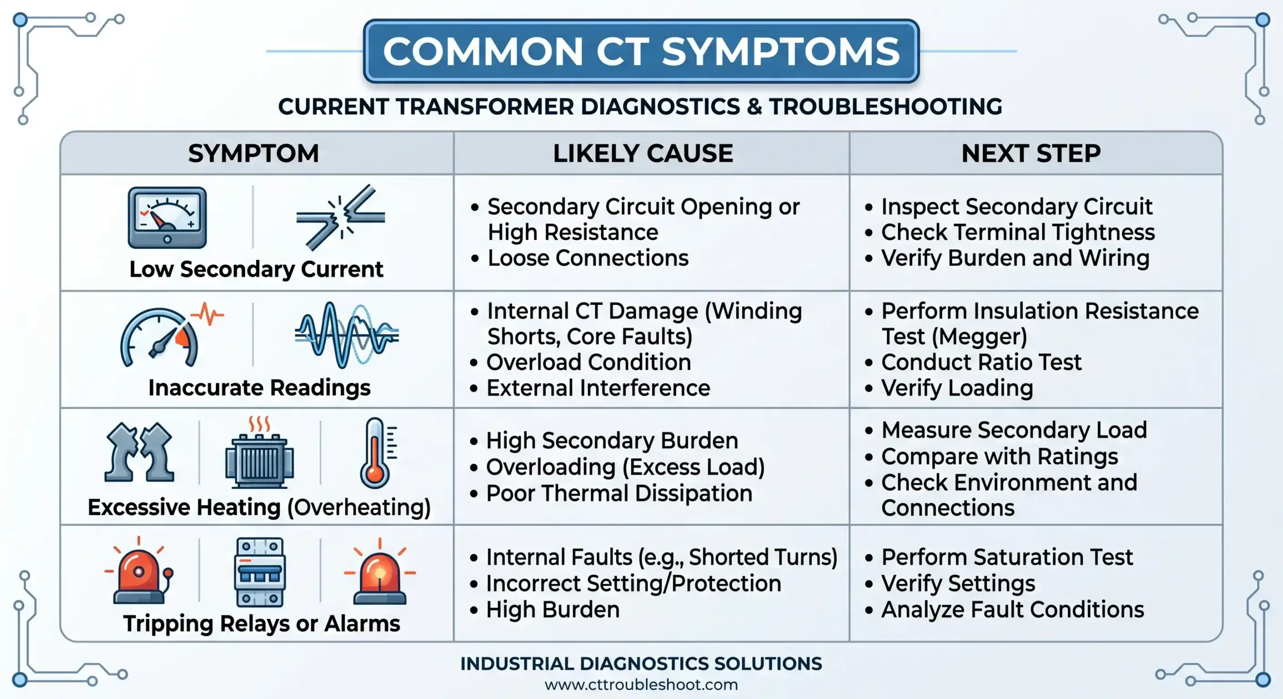
A helpful way to troubleshoot is to start from the symptom and work backward.
| Symptom | Likely Cause | Next Step |
|---|---|---|
| Meter reads too low | High burden, ratio error, saturation | Check wiring, burden, and ratio |
| Meter reads reversed | Polarity issue | Verify polarity marks and terminal arrangement |
| Relay trips incorrectly | Wrong CT connection, grounding error, saturation | Inspect circuits and test under load |
| CT secondary feels warm | Excessive burden or loose connection | Measure resistance and check terminals |
| Insulation test fails | Moisture or damaged winding insulation | Dry, clean, retest, or replace |
| Output becomes distorted at higher load | Core saturation | Confirm CT class and fault-performance needs |
This sort of symptom mapping is often the fastest path in the field.
Common CT Problems and How to Troubleshoot Them
1) Wrong readings
If the meter or relay displays values that do not align with the process, the first suspects are usually wiring and burden. A damaged CT is possible, but less common than a termination issue.
Useful checks:
– compare phase-by-phase readings
– confirm CT ratio settings in meters or relays
– inspect terminal blocks
– check secondary circuit resistance
2) Open or loose secondary wiring
A loose CT secondary connection can produce intermittent errors that come and go, which makes the fault annoying to catch. Heat, vibration, and corrosion often make the problem worse over time.
This is one of the reasons field technicians often torque-check the terminals after confirming safe isolation.
3) Saturation under fault or overload
Saturation deserves special attention in protection schemes. At high current, the magnetic core can stop reproducing the waveform accurately. This does not always mean the CT is bad; sometimes it simply means the application exceeds the CT’s design capability.
Signs of saturation:
– distorted secondary waveform
– relay behavior that changes only during high current events
– mismatch between expected and observed fault response
4) Grounding mistakes
Too many grounds, no grounds, or misplaced grounds can create all kinds of nuisance issues. In noisy industrial settings, grounding errors can look like random CT failure, when in reality the circuit reference is simply wrong.
5) Moisture, heat, and aging damage
Older CTs in switchgear rooms, rooftop cabinets, or outdoor enclosures often suffer from gradual insulation aging. Heat cycling and humidity do the damage slowly, which is why tests can look acceptable one year and questionable the next.
When Replacement Makes More Sense Than Repair
Some CTs can be put back into service after cleaning, re-terminating, or correcting the secondary circuit. Others should be replaced without much debate.
Replacement is often the better choice when:
– the ratio test fails repeatedly
– insulation resistance remains poor
– the housing is cracked or burned
– the core is mechanically damaged
– corrosion has reached the terminals or winding area
– the CT no longer matches the system burden or protection requirement
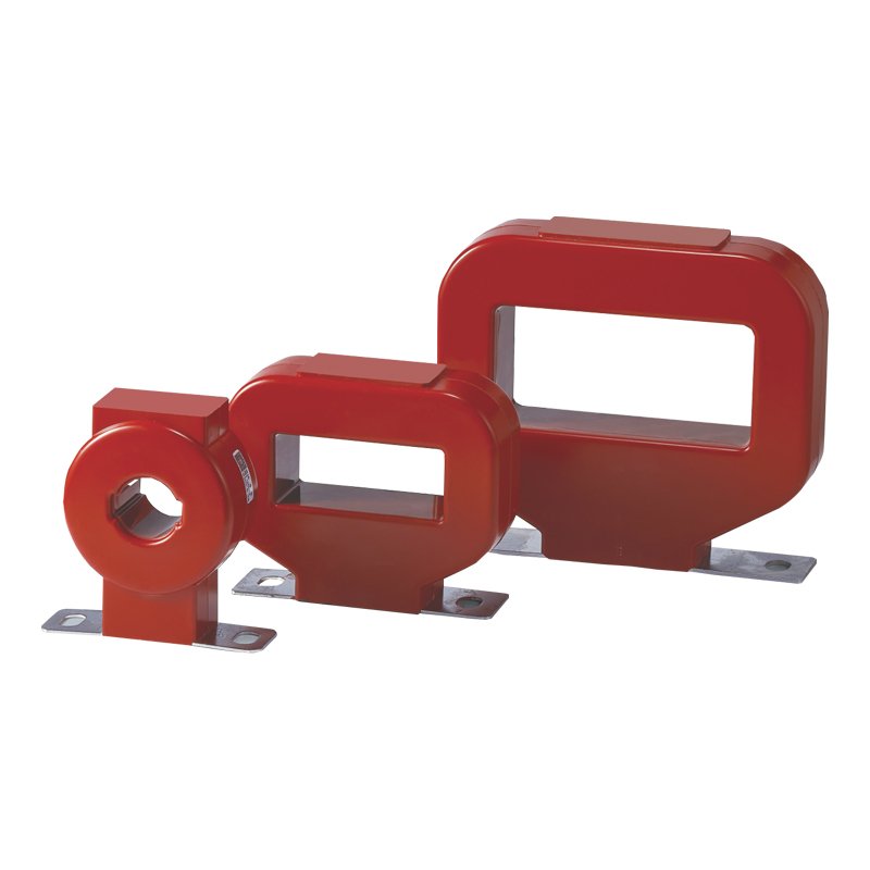
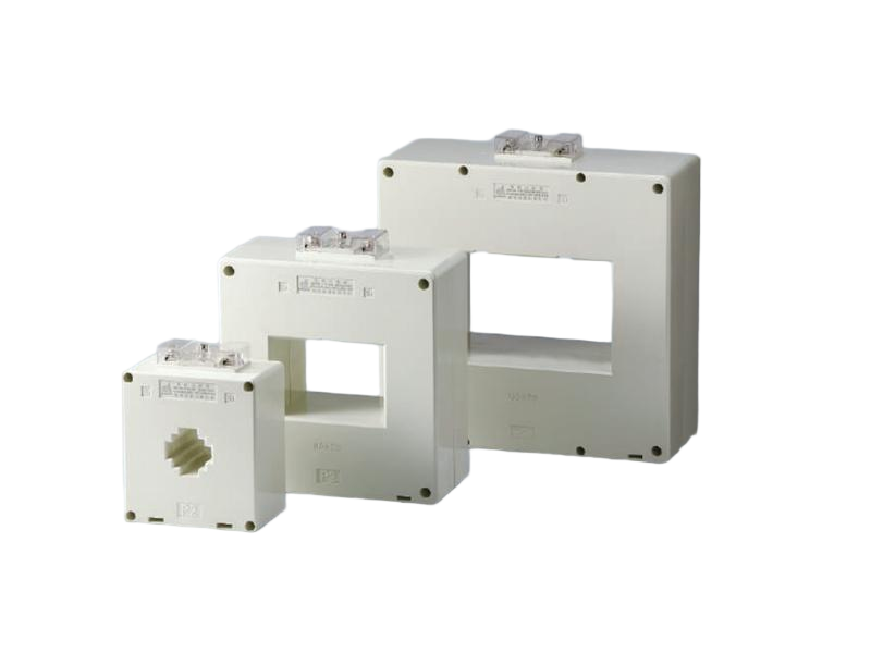
For replacement selection, the match needs to be more than just primary current. The mounting style, accuracy class, burden, and application all matter. Product categories such as Current Transformer,low voltage current transformer, high voltage current transformer, and Zero Sequence Current Transformer are typically chosen based on where and how the device will be used.
Choosing the Right Replacement CT
A replacement should be selected against the actual field requirement, not just a catalog headline. In practice, the most reliable choices are the ones that align with the electrical system and the intended function.
Consider:
– primary current rating
– secondary current rating
– accuracy class
– burden rating
– insulation level
– mounting and physical fit
– whether the CT is for metering, protection, or zero-sequence detection
A low-voltage cabinet, a medium-voltage feeder, and a ground-fault detection circuit do not need the same device, even if they look similar on paper.

Final Thoughts
On-site CT troubleshooting is usually most effective when it follows a simple logic: verify safety, confirm wiring, test the secondary circuit, check ratio and polarity, and then look at burden and operating conditions. In many cases, the current transformer itself is not the real problem. The wiring around it, the load on it, or the conditions it works in are what cause trouble.
A careful field check saves time, reduces nuisance trips, and avoids replacing equipment that is still perfectly serviceable. And when replacement is needed, choosing the right CT for the application matters just as much as the test itself.
If you’d like, a process flowchart or a simple diagnostic diagram can be created next to make this article easier to use in the field.
FAQ
How often should a CT be verified in a critical installation?
Critical systems are usually checked on a maintenance schedule tied to risk, loading, and environmental exposure. Equipment in harsh conditions or with tight protection margins tends to justify more frequent verification than lightly loaded metering points.
Can a CT be checked without shutting down the whole system?
Sometimes, yes. Certain non-intrusive checks can be done with clamp measurements, relay diagnostics, or secondary-side inspection, but any direct CT secondary work still needs proper isolation and safety controls. The approach depends on the site design and maintenance rules.
What suggests a protection CT is saturating rather than simply failing?
Saturation usually appears only under higher current events, especially faults or overloads. The CT may test normally at low current, yet the waveform becomes distorted when demand rises. A true failure is more likely to show up as a persistent ratio, continuity, or insulation problem.