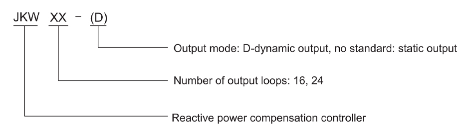
Table of Contents
Code and Implication
Application
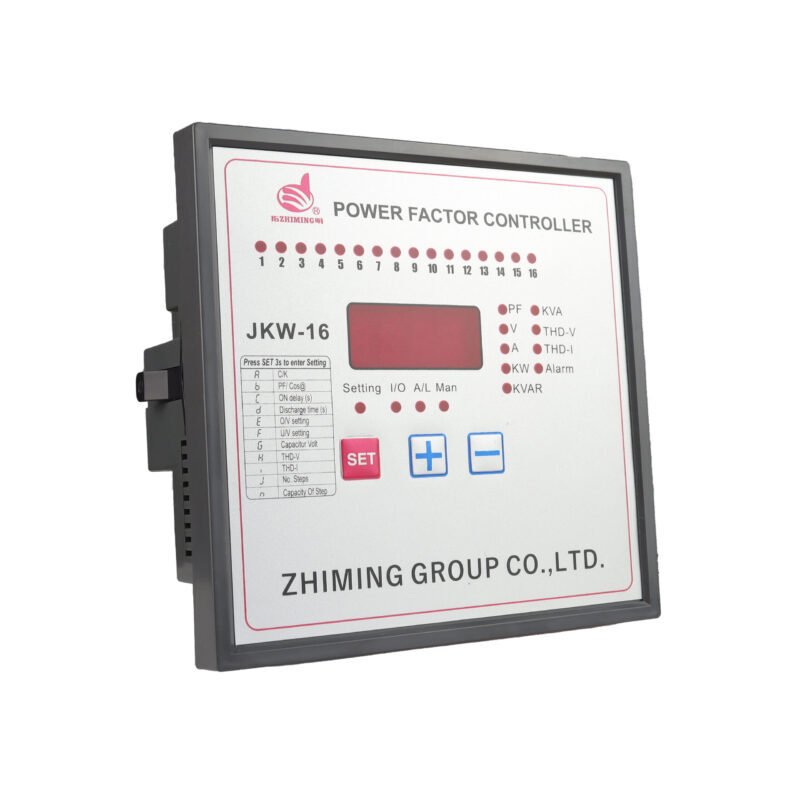
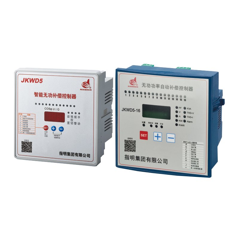
ZHIMING brand of JKW Reactive Power Compensation Controller is designed for self-regulating capacitor banks in low-voltage distribution systems. It enhances power transformer operating efficiency, reduces line losses, and improves voltage regulation – ultimately increasing ROI and grid reliability through optimized power factor correction.
Structure Features
● Adopt AC sampling technology.
●Digital integration, filtration, not sensitive to the harmony wave.
● Regarding the reactive power as a controlling physical quantity, it has high control precision.
● The operation of the full digital control parameter, easy to use, put in the right place in one step, and the data is not lost in case of a power failure.
● Adopt and optimize the excellent control scheme automatically, reduce the number of inputs and cutoff, and improve the service life of the system.
● Strong anti-interference ability can resist 2000V interference pulse from direct power, and not crash, does not lose the data, and it is able to run steadily.
● Digital display of electric network power factors, reactive power, voltage, current (primary side), and control parameter.
● With two working modes of manual and automatic is convenient for the user to install and debug.
● With the function of over-voltage, under-voltage judgment, and display and fast cutoff capacitor group, prevent the capacitor group from running under the over-voltage condition.
● With the function of available input and cutoff shocking and locking.
● The function for the delay time of the selectable single group capacitor for 200 seconds from the cutoff input, which makes the capacitor have abundant discharging time after cutoff and reduces the impact on the electric net when put back into use again.
● The input resistance of the current sampling signal is smaller than 0.05Ω; it can be taken out from the measuring loops directly.
● Output Loops 1-12 Loop.
Technical Parameter
| Parameter | Specification |
| Rated Voltage | AC 380V +10% (IEC 60038) |
| Rated Current | AC 0-5A (max. continuous) |
| Rated Frequency | 50Hz ±5% |
| Control Parameters | |
| ▶ Sensitivity | 100mA (min. operating current) |
| ▶ Target PF Setting | 0.70-0.99 (adjustable, 0.01 resolution; factory default: 0.98) |
| ▶ Switching Delay | Transient mode: 0.5ms-200s |
| Steady-state mode: 2-200s | |
| ▶ CT Ratio Range | 50:5 to 3000:5 (1:1 resolution; factory default: 500:5) |
| ▶ Output Capacity | Transient: DC 12V @ 50mA/channel |
| Steady-state: 380V AC @ 7A/channel or 200V AC @ 5A/channel | |
| Measurement Accuracy | |
| ▶ Voltage | Class 1.0 (±1.0% of reading) |
| ▶ Current | Class 1.0 (±1.0% of reading) |
| ▶ Power Factor | ±1.0% |
| ▶ Reactive Power | Class 2.0 (±2.0% of reading) |
Product Size
Panel Cut-out Dimensions
| Controller Model | Cutout Dimensions (H × W) | Tolerance | Mounting Notes |
| JKWD5-16 | 138.0 × 138.0 mm | ±0.5 mm | Square cutout with radius ≤0.5 mm at corners |
| JKWD5 | 113.0 × 113.0 mm | ±0.5 mm | Max. panel thickness: 3.0 mm |
Critical Installation Requirements:
1. Surface Flatness: ≤0.5 mm across cutout area
2. Edge Finish: Burr-free (max. Ra 6.3 μm)
3. Clearance: ≥20 mm behind panel for wiring termination
4. Sealing: Apply an IP54 gasket (included) when used in polluted environments
Engineering Drawing Notation:
| JKWD5-16 Ø4.3×4 M4 Mounting Holes (typical) |
Fig. 1: Standard cutout with M4 fastener positions (all dimensions in mm)
Wiring Diagram