Table of Contents
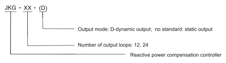
Code and Implication
Application
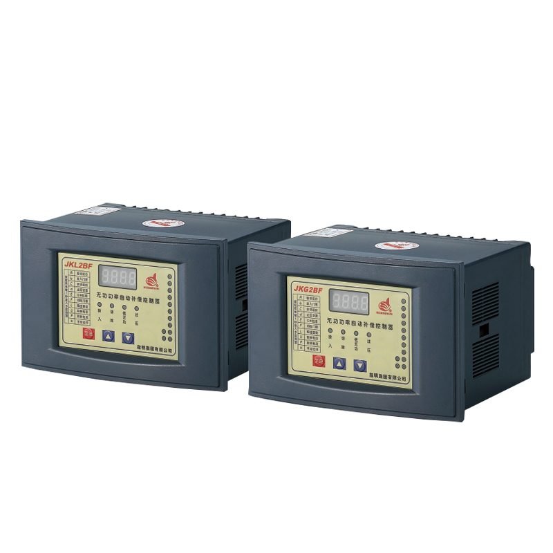
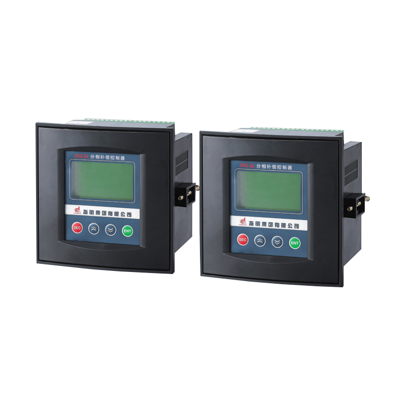
ZHIMING brand of JKG Series Phase-Separation Compensation Controller.
The JKG series is a new-generation phase-separation compensation capacitor controller designed for reactive power management in 0.4 kV, 50 Hz AC distribution systems. It integrates data acquisition, reactive power compensation, and system parameter analysis into a compact, intelligent unit.
Featuring a high-speed digital signal processor (DSP), the JKG controller performs precise real-time AC sampling. Its 128×64 matrix LCD provides an intuitive interface for system monitoring, reactive compensation control, harmonic analysis, and adaptive frequency tracking. The device supports input frequency ranges from 45 Hz to 55 Hz, ensuring stable operation under varying grid conditions.
Termination function
Real-Time Data Monitoring
- Phase A/B/C voltage, current, and power factor
- Switching the status (ON/OFF) of capacitors for Phase A/B/C
- Active and reactive power for Phase A/B/C
- Total harmonic distortion (THD) of voltage and current waveforms (Phase A/B/C)
- System frequency
Harmonic Analysis
- Harmonic content (3rd, 5th, 7th, 9th, 11th, 13th) of phase voltage
- Harmonic content (3rd, 5th, 7th, 9th, 11th, 13th) of phase current
Reactive Power Compensation
- Reactive power as the core control variable (sampling parameter)
- No switching oscillation during capacitor group operation
- Supports multiple compensation modes:
- Y-type compensation
- A-type compensation
- Combined Y+A compensation
Environmental Conditions
- Ambient Operating Temperature: −25°C to +65°C
The device is designed to operate reliably within this temperature range without performance degradation. - Relative Humidity: Up to 90% at +20°C
Higher relative humidity is permissible at lower ambient temperatures. The device should not be subjected to condensation. - Altitude: Installation site altitude shall not exceed 2500 meters above sea level.
For installations above this altitude, derating or additional environmental protection measures may be required. - Atmospheric Conditions at Installation Site:
- The installation site must be free from flammable or explosive substances.
- No conductive dust or corrosive gases (such as hydrogen sulfide, chlorine, ammonia, etc.) should be present in the air.
- Adequate ventilation should be ensured to maintain internal temperature within operational limits.
Main Technical Data
Termination Function
- Supply Voltage: AC 220V ±20% / AC 380V ±20%
- Sampling Voltage: AC 220V ±20% / AC 380V ±20%
- Power Frequency: 50Hz ±5%
- Sampling Current: 0–5A
Maximum Power Consumption
- 20W (depending on the power rating of the switching device)
Control Output Contacts
- 24 switching channels, each with DC 12V × 30mA output
Measurement Accuracy
- Voltage: ±0.5%
- Current: ±0.5%
- Active Power: ±1.0%
- Reactive Power: ±1.0%
- Frequency: ±0.5%
- Power Factor: ±1.0%
Control Parameters
- Control Sensitivity: 30mA
- Target Power Factor (COSφ1): 0.85–1.00 (step: 0.01, default: 1.00)
- Target Power Factor (COSφ2): 0.00–0.60 (step: 0.01, default: 2.2)
- Threshold Coefficient: 0.5–1.2 (step: 0.1, default: 1.00)
- Switching Delay (1): 0–600s (step: 1s / 0.02s, default: 30s)
- Switching Delay (2): 0–300s (step: 1s, default: 30s)
- Overvoltage Protection: 230–280V / 400–480V (step: 1V, default: 240V / 430V)
- Undervoltage Protection: 180–210V / 300–360V (step: 1V, default: 190V / 330V)
- Harmonic Voltage Over-limit: 0.0%–25.0% (step: 0.5%, default: 0.0%)
- Harmonic Current Over-limit: 0.0%–100.0% (step: 0.5%, default: 0.0%)
Product Size
Specification & Dimensions
Panel Cutout Dimensions for JKG-24 Model
- Opening Dimensions: 138 mm × 138 mm (W × H)
- This refers to the required cutout size in the panel or enclosure for proper flush mounting of the JKG-24 power factor controller. Ensure the panel cutout is clean and precise to guarantee secure installation and optimal display visibility.