Table of Contents
Model and implication
| Position | Description | Definition |
| ZMTBB | Manufacturer Code + Complete Equipment | ZMT series complete set of high voltage shunt reactive power compensation device |
| □□□ | Unit Capacity (kvar) | Capacity per single capacitor unit (in kilovolt-ampere reactive) |
| □□□□ | Total Rated Capacity (kvar) | Total rated reactive power output of the device |
| □□□ | System Voltage (kV) | Nominal system voltage in kilovolts |
| A / B | Main Wiring Method | A = Single Star Connection B = Double Star Connection |
| K / C / L / Q / Y | Relay Protection Mode | K = Open Delta Protection C = Voltage Differential Protection L = Unbalanced Current Protection Q = Bridge Differential Current Protection Y = Unbalanced Voltage Protection |
| % / L | Reactance %: “L” means harmonic filtering included | Reactance percentage value; “L” indicates harmonic filtering reactor is included |
| W | Installation Type:W = Outdoor(Blank = Indoor) | W = Outdoor Installation (If omitted, indicates indoor installation) |
Application
ZHIMING brand of The ZMTBB High Voltage Fixed Reactive Power Compensation Device is designed for use in 6–35kV, 50Hz AC power systems. It is primarily used to regulate bus voltage, provide reactive power compensation, improve power factor, enhance voltage quality, and reduce power network losses.
Application Notes
- Applicable for 6~35kV high-voltage power systems.
- Improves power factor and reduces reactive power loss.
- Optional filtering reactors help mitigate harmonics.
- Protection mode is customizable based on project demand.
Standards of Compliance
- GB 50227-2008: Code for Design of Shunt Capacitor Devices
- JB/T 7111-1993: High Voltage Shunt Capacitor Device
- JB/T 10557-2006: High Voltage Reactive Power Local Compensation Device
- DL/T 604-1996: Technical Specifications for Ordering High Voltage Shunt Capacitor Devices
Main Technical Performance Indicators
Capacitance Tolerance
- The deviation between actual and rated capacitance is within 0 to +5%.
- The ratio between the maximum and minimum capacitance values among any two terminals shall not exceed 1.02.
Inductance Tolerance
- At rated current, the allowable deviation of reactance is 0 to +5%.
- The inductance value of each phase shall not exceed +2% of the three-phase average value.
Insulation Level
- Power Frequency Withstand Voltage: According to applicable system voltage (e.g., 6kV: 32kV/1min, 10kV: 42kV/1min)
- Lightning Impulse Withstand Voltage: Follows IEC standards (e.g., 6kV: 60kV BIL, 10kV: 75kV BIL)
- Creepage distance and insulation clearances meet GB and IEC standards
Operating Environment Conditions
- Cabinet-type units are installed indoors; frame-type units are generally installed outdoors.
- Installation altitude should not exceed 1000 meters. For higher altitudes, please consult with the manufacturer.
- Ambient temperature range:
- Indoor device: −25°C to +45°C
- Outdoor device: −40°C to +45°C
- Installation location must be free from severe mechanical vibration, corrosive gases, vapors, or conductive/explosive dust.
- The connected power network or busbar should not be affected by high-order harmonics. Voltage waveform distortion and harmonic content must comply with GB/T 14549-93 “Power Quality – Public Grid Harmonics.”
Structure and Working Principle
Device Structure & Switching Modes
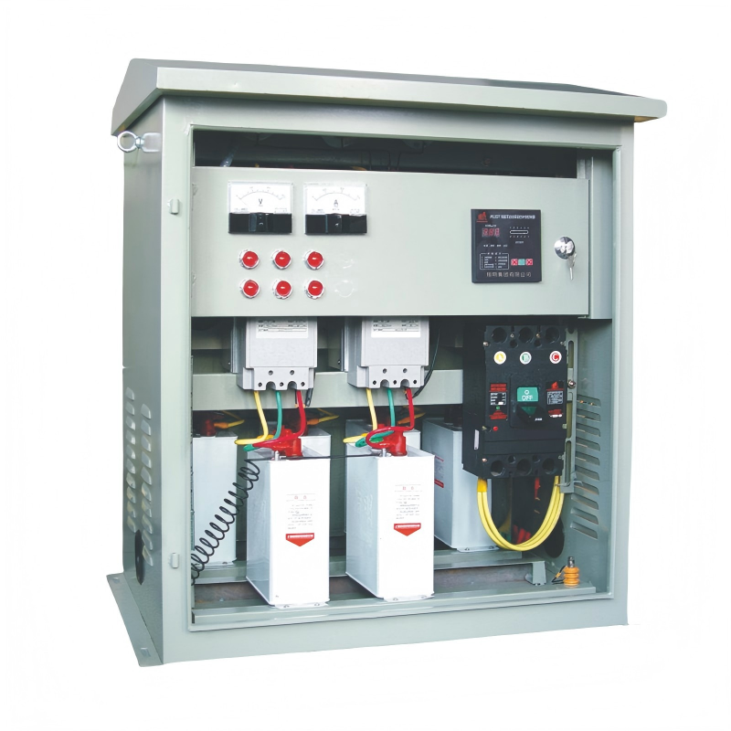
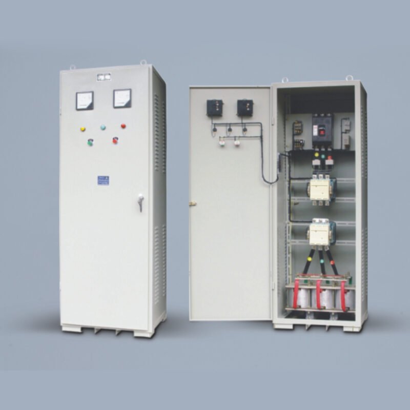
The device is available in either cabinet-type or open-frame construction. Capacitor banks can be switched manually or automatically using a voltage-reactive power automatic controller.
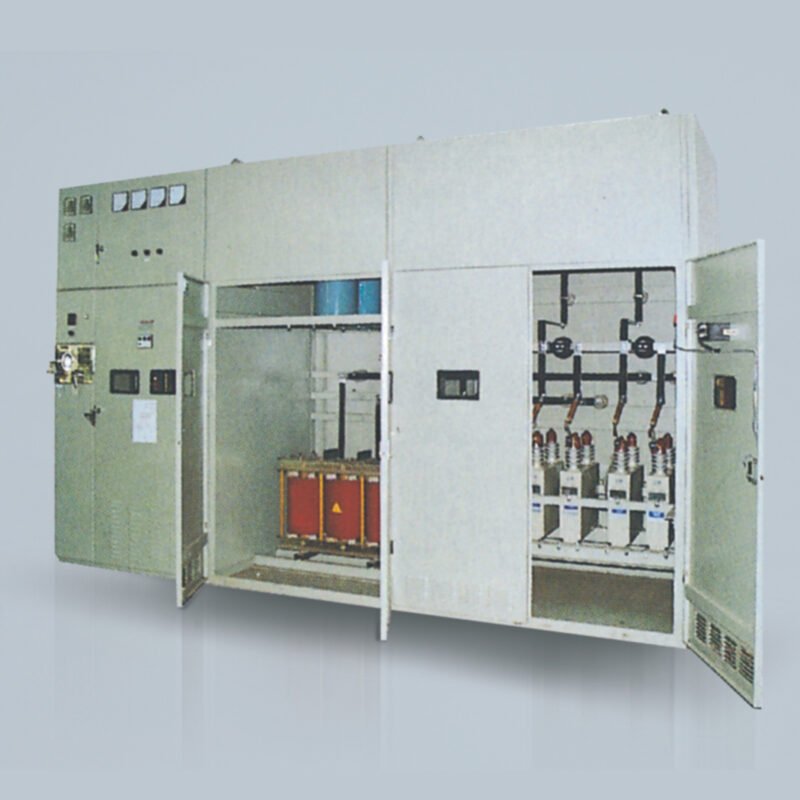
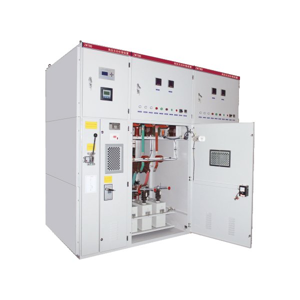
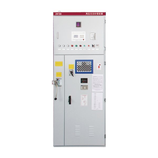
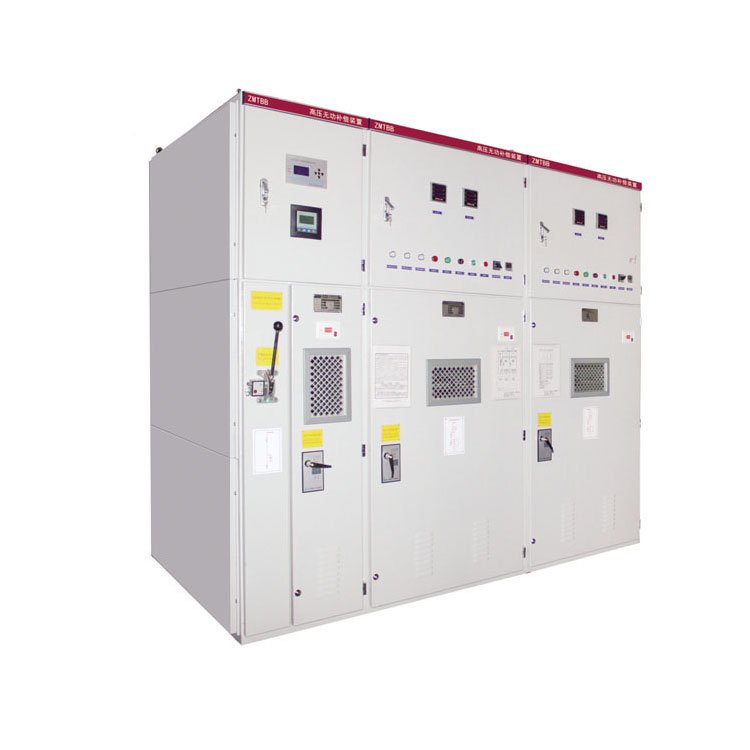
Cabinet-Type Structure
This configuration consists of an incoming isolator cabinet, a series reactor cabinet, a shunt capacitor cabinet, and interconnecting busbars.
The number of capacitor cabinets is determined by the required compensation capacity and system design, typically involving multiple cabinets.
The cabinet is made from high-quality cold-rolled steel sheets or aluminum-zinc coated sheets, formed and welded or assembled.
Protection rating: IP20.
Internal Layout
For single capacitor units rated 30–100 kvar, a three-tier single/double row configuration is used.
For units above 100 kvar, a two-tier single/double row structure is applied.
For units above 200 kvar, a single-tier single/double row design is adopted.
Frame-Type Structure
This design includes:
Isolator frame, dry-type air-core reactors, shunt capacitor racks, and protective fencing.
Components include: zinc oxide surge arresters, shunt capacitors, individual protection fuses, sealed discharge coils, post insulators, copper (or aluminum) busbars, and a galvanized metal frame.
Capacitor banks are mounted on the frame, interconnected via busbars and post insulators to form the primary circuit.
Frame-type assemblies are modular for easy transportation, stable in structure, and material-efficient.
Typical installation options: single-row three-tier, double-row single-tier, or double-row two-tier.
Each capacitor phase is usually connected in parallel first, then in series.
Frame surfaces are treated with hot-dip galvanizing or powder coating.
A 1.8-meter-high protective fence is installed as needed and coated for durability.
Frame materials are made of high-quality structural profiles.
Series Reactor Selection
Dry-type iron-core reactors are typically installed at the neutral point side.
Air-core reactors are installed on the power supply side, either in a stacked three-phase or triangular (delta) layout.
Secondary Protection & Control
A microprocessor-based protection and monitoring device is installed on the upstream HV switchgear. It supports both manual and remote automatic control modes, which are mutually interlocked.
For automatic switching, a voltage-reactive power controller or power factor controller is used. It performs sampling, logic analysis, and controls the capacitor switching accordingly.
The controller is equipped with RS232 or RS485 communication interfaces, allowing integration into a substation’s automation system to support unattended or centralized monitoring modes.
Interlocking & Safety Requirements
The incoming switchgear features mechanical and electrical interlocks between the earthing switch and circuit breaker.
Each capacitor unit is equipped with electromagnetic locks and cabinet door locks for safety.
Operation is prohibited if any door is not securely closed. Attempting to do so will cause the main breaker to trip immediately.
For frame-type units, users must equip the isolator operating mechanism and fence doors with mechanical code locks, interlocked with upstream breakers to prevent maloperation.
The fence must be securely closed and locked before operation, and must remain closed during operation.
| Type | Rated Parameters | Configured Capacitor Models | Dimensions (mm) (L×W×H) | ||
| Ue(kV) | le(A) | Qe(kvar) | |||
| 2×ZMTBB-10-1200/200-AK | 11/ √3 | 63 | 1200 | BAM11/ √3-200-1 | 7600×1400×2600 |
| 2×ZMTBB-10-1404/234-AK | 11/ √3 | 73.6 | 1404 | BAM11/ √3-234-1 | |
| 2×ZMTBB-10-1500/250-AK | 11/ √3 | 78.4 | 1500 | BAM11/ √3-250-1 | |
| 2×ZMTBB-10-1602/267-AK | 11/ √3 | 84 | 1602 | BAM11/ √3-267-1 | |
| 2×ZMTBB-10-1800/300-AK | 11/ √3 | 94.4 | 1800 | BAM11/ √3-300-1 | |
| 2×ZMTBB-10-2004/334-AK | 11/ √3 | 105 | 2004 | BAM11/ √3-334-1 | |
| 2×ZMTBB-10-2400/400-AK | 11/ √3 | 126 | 2400 | BAM11/ √3-400-1 | |
Ordering Information
When placing an order for the shunt capacitor compensation device, please provide the following details:
- Model Number, Specifications, and Quantity
- Exact model designation and rated parameters
- Required capacity, voltage level, and any variant codes
- Power Network Harmonic Data
- Nominal system voltage and current levels
- Measured or anticipated harmonic spectrum (order and amplitude)
- Any requirements for discharge coils, series reactors, or additional filtering elements
- Primary Wiring Scheme and Protection Configuration
- Preferred connection type (e.g., Y or Y–Y, neutral non-grounded)
- Secondary protection logic and relay types
- Capacitor Room Layout Drawings
- Plan view showing the relative positions of switchgear, capacitors, reactors, etc.
- Elevation/sectional view depicting mounting heights and clearances
- Cable Entry Method
- Entry orientation: top, bottom, left, or right
- Entry type: cable entry or busbar entry
- Short-Circuit Capacity (Sd)
- Available short-circuit MVA or current at the installation point
- Site Conditions
- Installation altitude above sea level
- Ambient temperature range and extremes
- Air quality/environmental factors (e.g., pollution level, corrosive gases, dust)
- Delivery Schedule and Transportation
- Desired delivery date or time window
- Preferred shipping/transport method (road, rail, sea, etc.)
- Special Technical or Functional Requirements
- Any atypical specifications, certifications, or interface requirements
- If control/communication integration is needed, specify protocols or interfaces
For bespoke configurations or further consultation, please contact our engineering department with as much detail as possible. This ensures accurate design, timely delivery, and optimal performance.
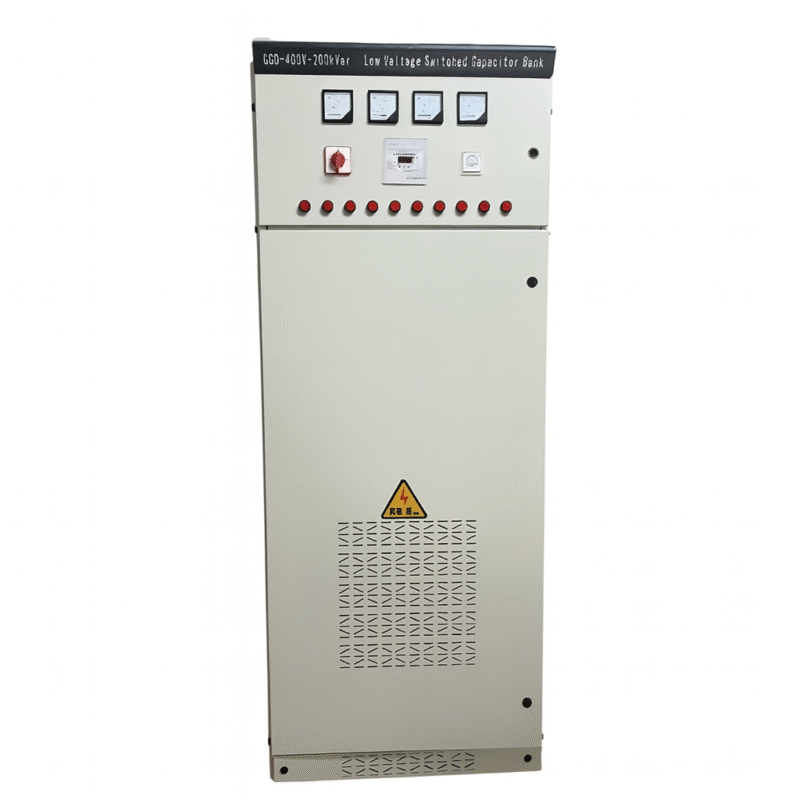
External Structure & Dimensions
- The device can be constructed as an indoor metal-enclosed cabinet or an outdoor open-frame structure.
- Cabinets are typically used for indoor substations and industrial applications.
- Frame-type enclosures are used outdoors and are designed for weather resistance and ease of maintenance.
- Customization available based on rated capacity, protection configuration, and site layout.
Note: External dimensions and base mounting hole positions vary depending on model and rated capacity. Detailed engineering drawings are available upon request.
Outline and Mounting Dimensions of Shunt Capacitor Bank

Internal Structure of Shunt Capacitor Compensation Device
Overload Capacity
Steady-State Overvoltage
| Operating Voltage (×UN) | Maximum Duration | Description |
| 1.10 | Continuous | Maximum long-term steady-state overvoltage |
| 1.15 | 30 minutes per 24 hours | Voltage fluctuation due to system regulation |
| 1.20 | 5 minutes | Voltage rise during light load |
| 1.30 | 1 minute | Voltage rise during light load |
Steady-State Overcurrent
The device can operate continuously under an RMS current not exceeding 1.1 × 1.3 × IN.
Transient Overvoltage and Overcurrent During Switching
When switching capacitors using non-inrush-limited switches, the first peak of transient overvoltage must not exceed 22 times the RMS applied voltage, and the duration must not exceed 12 cycles. The corresponding peak transient overcurrent may reach 100 times the rated current (100 IN). Under such conditions, up to 1000 operations per year are permitted.
Maximum Permissible Capacity
Within the limits of 5.4.1 and 5.4.2, the total operating capacity shall not exceed 1.35 × ON.
Discharge Performance
After power-off, the residual voltage on each capacitor group shall drop below 50V within 5 seconds.
Internal Fault Protection
The device is equipped with individual fuses (or internal fuse links) for each capacitor unit. In addition, different relay protection schemes are implemented depending on the main wiring method.
System Fault Protection
The device includes protection functions against: Overcurrent, Overvoltage, Undervoltage
Rated Capacity & Dimensions
Both the rated capacity and overall dimensions of the device are customizable based on user specifications.
Primary Circuit Wiring of the Compensation Device
Wiring Method
The compensation device supports two wiring configurations: “Y” (single star) and “Y–Y” (double star) connections.
The neutral point is non-grounded in both configurations.
For detailed connection methods, please refer to the primary wiring diagram and the single-line system schematic provided for each product model.

*The connection method places the reactor on the neutral point side of the capacitor group.