It is very unusual for electrical systems to work perfectly without any issues. Loads turning on and off, motors starting hard, lights tending to be very different, and facilities using far more reactive power than you may want. This is when an **APFC (automatic power factor controller)** is useful. An APFC does not make a very big scene but instead helps keep your power factor closer to your goal. Most times, a properly set up APFC will do its job without needing to be managed closely by the operator.
To put it simply, a controller monitors an electrical system and determines how many reactive power are required; then it connects/disconnects capacitor stage(s) as the conditions change. This sounds straightforward, but it’s actually the logic that drives it that makes it all work.
Índice
O que faz realmente um controlador automático do fator de potência
An automatic power factor controller is designed to keep power factor near a preset value by managing capacitor banks in real time. When a system becomes more inductive, the controller compensates by switching in capacitors. When the load drops or the system approaches the desired value, it removes some compensation.
A useful way to think about it is this: the controller acts like a feedback system that keeps checking whether the electrical network is leaning too far toward reactive consumption. If it is, the controller corrects that imbalance before it grows into penalties, inefficiency, or unstable voltage behavior.
For facilities looking at controller options, the controlador automático do fator de potência category typically covers the core device that performs this monitoring and switching task.
The Working Principle, Step by Step
The logic is not complicated, but it does rely on continuous measurement and quick decision-making.
1. It measures voltage and current
The controller receives input from current transformers and voltage signals. From these, it calculates the system’s present power factor, usually by assessing the phase relationship between voltage and current.
This is the part that often gets overlooked. The controller is not guessing. It is reading the electrical behavior of the load and comparing it against a target.
2. It compares actual power factor with the set point
Once the system’s condition is known, the controller checks how far it is from the desired value. If the power factor is lagging too much, compensation is needed. If the system is already close to the target, no change is necessary.
That comparison is repeated continuously. In real installations, loads are rarely steady for long, so this loop matters more than it first appears.
3. It switches capacitor stages automatically
This is the heart of the process. The controller sends signals to contactors or thyristor switching devices, bringing capacitor stages in or out as required. Usually, compensation is staged rather than abrupt.
That staging is helpful because a single large step could overshoot the correction and create a leading power factor. By working in steps, the controller keeps the system more stable.
4. It keeps adjusting as conditions change
The loop never really stops. As machinery starts, stops, or moves into light-load operation, the controller re-evaluates the situation and responds again.
The ability for the system to continually adjust itself, thus making it automatic, not just simply reactive, is its main advantage. It can respond to changes in load conditions all the time, without requiring an operator nearby to manually turn things on and off.
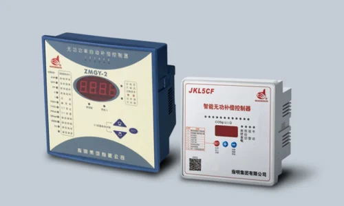
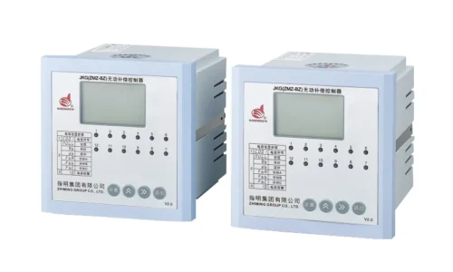
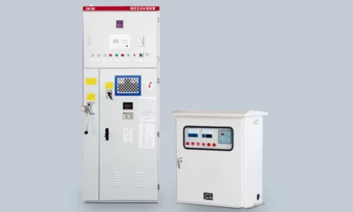
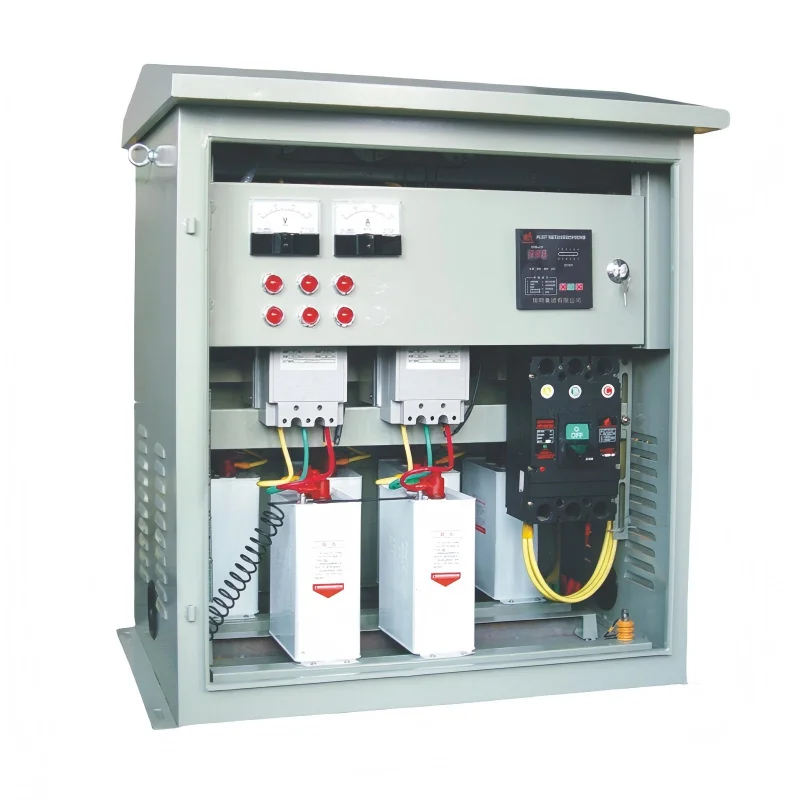
Main Components Inside the System
Although models differ, most setups include a similar set of parts:
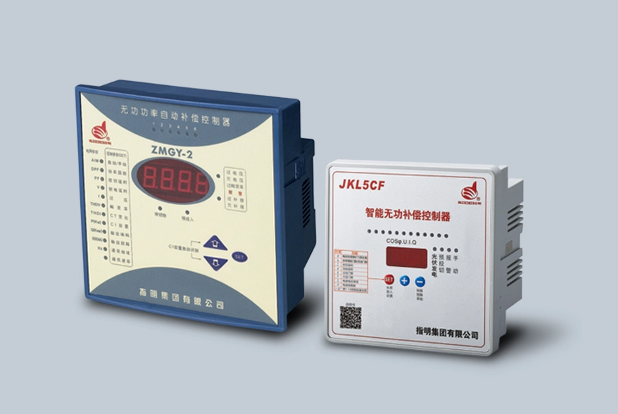
- Controller unit: the brain that makes the switching decisions
- Current transformers: measure load current
- Voltage sensing input: provides the electrical reference
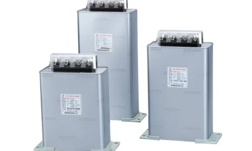
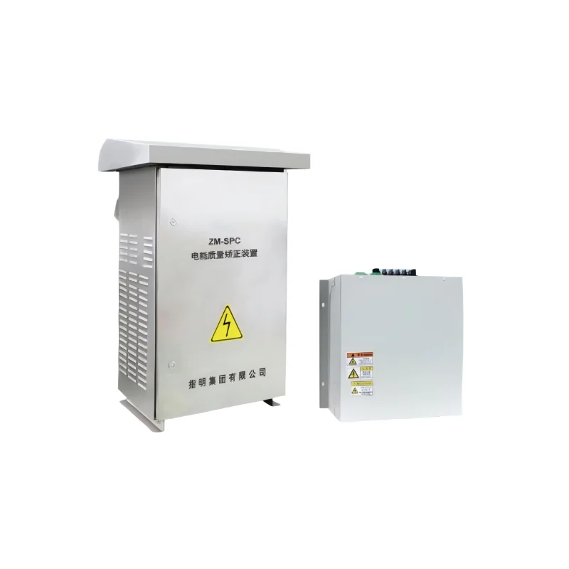
- Capacitor bank: supplies reactive compensation
- Switching devices: connect or disconnect capacitor steps
- Protection elements: guard against overloads or abnormal conditions
In some products, the control logic is built into a broader reactive power compensation controller, which ties sensing, decision-making, and switching together in one coordinated unit.
Why It Matters in Real Facilities
The practical value of power factor correction is often clearer on the shop floor than in a textbook. Facilities that run motors, pumps, HVAC systems, welding equipment, or variable-frequency drives tend to see reactive power rise and fall throughout the day.
A well-tuned automatic power factor controller can help by:
- lowering apparent power demand
- reducing utility penalty charges
- improving voltage stability
- freeing up transformer and cable capacity
- reducing unnecessary heating in the electrical network
That list may sound like routine efficiency language, but in practice it can affect equipment life and operating cost in a very direct way. Even a moderate improvement can make the system feel less strained.
Manual vs Automatic Power Factor Compensation
| Aspeto | Manual Compensation | Controlador automático do fator de potência |
|---|---|---|
| Response speed | Slow | Fast |
| Exatidão | Depends on operator timing | Consistent and adaptive |
| Labor requirement | Mais alto | Inferior |
| Risk of over/under correction | More likely | Reduzido |
| Melhor para | Stable loads | Cargas variáveis |
For facilities with changing demand, the automatic approach is usually the more practical one. Manual capacitor switching can work in simpler systems, but it tends to become inconvenient once load patterns start shifting throughout the day.
When Harmonics Change the Picture
Not every electrical environment is clean. In many modern plants, harmonics from rectifiers, inverters, computer loads, or drives can interfere with power factor correction. In those cases, a standard capacitor bank may need additional thought, because capacitors and harmonics do not always coexist peacefully.
This is where harmonic-aware solutions become relevant. A Compensation Capacitor Harmonic Controller is typically used in situations where distortion needs to be managed along with reactive power.
When harmonics are present, the controller has to do more than simply chase a target power factor. It also needs to avoid resonance, reduce capacitor stress, and keep the correction system stable. That extra layer of protection can be important in industrial plants, data-heavy buildings, and sites with a lot of power electronics.
Choosing the Right Controller for an Installation
The best setup depends on the load profile, not just the nominal electrical rating. A few factors usually matter more than people expect:
- Load variation – Is the plant steady or constantly changing?
- Number of capacitor stages – More stages can mean finer control.
- Harmonic content – Distorted systems may need detuned or harmonic-capable equipment.
- Switching method – Contactor-based or fast electronic switching.
- Monitoring and protection – Useful for long-term reliability.
There is a tendency to focus only on size, but that is only part of the story. The controller should match the actual operating behavior of the facility.
Common Misunderstandings
A few assumptions come up again and again:
| Common misunderstandings | A more accurate view |
|---|---|
| It only saves electricity | Not exactly. It also helps with capacity utilization and system stability |
| Any capacitor bank will do | Not really. The controller logic and system conditions matter a lot |
| Once installed, it can be forgotten | Mostly true for operation, but periodic checks are still sensible, especially in changing industrial environments |
Se quiser saber mais sobre um controlador automático do fator de potência, leia o que é um controlador automático do fator de potência?
FAQ
How is the target power factor chosen?
It is usually set based on utility requirements, site operating goals, and the behavior of the connected load. In some facilities, the best value is not the theoretical maximum, but a practical range that avoids overcompensation.
Can the controller handle loads that change throughout the day?
Yes. That is one of its main strengths. Variable demand is actually where automatic compensation tends to outperform manual switching, because it can respond as loads rise and fall.
Do harmonic-rich systems need special care?
Often, yes. If the network includes VFDs, converters, or other nonlinear loads, harmonic filtering or detuned compensation may be needed to keep capacitors from being overstressed.