A maioria dos gestores de instalações não passa muito tempo a pensar no fator de potência - até aparecer uma penalização na fatura da eletricidade. Normalmente, é nessa altura que a conversa começa. Mas a verdade é que um fator de potência fraco tem vindo a custar dinheiro e a sobrecarregar o equipamento muito antes de alguém dar por isso.
A controlador do fator de potência existe para resolver exatamente esse problema. Monitoriza o sistema elétrico em tempo real e compensa automaticamente a energia reactiva, mantendo o fator de potência o mais próximo possível da unidade. O conceito é simples, mas os efeitos a jusante sobre os custos, a eficiência e a saúde do equipamento são significativos.
Índice
Compreender o fator de potência (e porque é que diminui)

O fator de potência é essencialmente uma medida da eficácia com que a energia eléctrica está a ser utilizada. Num mundo ideal, toda a energia retirada da rede faria um trabalho útil - accionando motores, iluminando espaços, alimentando compressores. Na realidade, uma parte dessa energia apenas se desloca entre a fonte e a carga sem realizar nada de produtivo. É a energia reactiva.
Os culpados são quase sempre cargas indutivas. Motores, transformadores, balastros de lâmpadas fluorescentes, fornos de arco - tudo o que tenha bobinas ou enrolamentos consome energia reactiva para além da energia real de que necessita. Quanto mais cargas indutivas houver num sistema, pior será o fator de potência.
Eis uma forma rápida de pensar sobre os três tipos de energia envolvidos:
| Tipo de alimentação | Símbolo | Unidade | O que representa |
|---|---|---|---|
| Poder real | P | kW | Trabalho útil efetivo realizado |
| Potência reactiva | Q | kVAR | Energia armazenada e devolvida por cargas indutivas/capacitivas |
| Potência aparente | S | kVA | Potência total absorvida da rede (combinação de P e Q) |
A relação entre estes três factores é o que determina o seu fator de potência. Um fator de potência de 1,0 significa que toda a potência aparente está a fazer trabalho real. Se baixar para 0,7 ou 0,6, uma parte substancial do que está a consumir é essencialmente desperdiçada do ponto de vista da faturação.
O Departamento de Energia dos EUA publicou orientações sobre este tópico, e a conclusão é consistente: o baixo fator de potência é uma das fontes de ineficiência mais negligenciadas nos sistemas eléctricos industriais e comerciais.
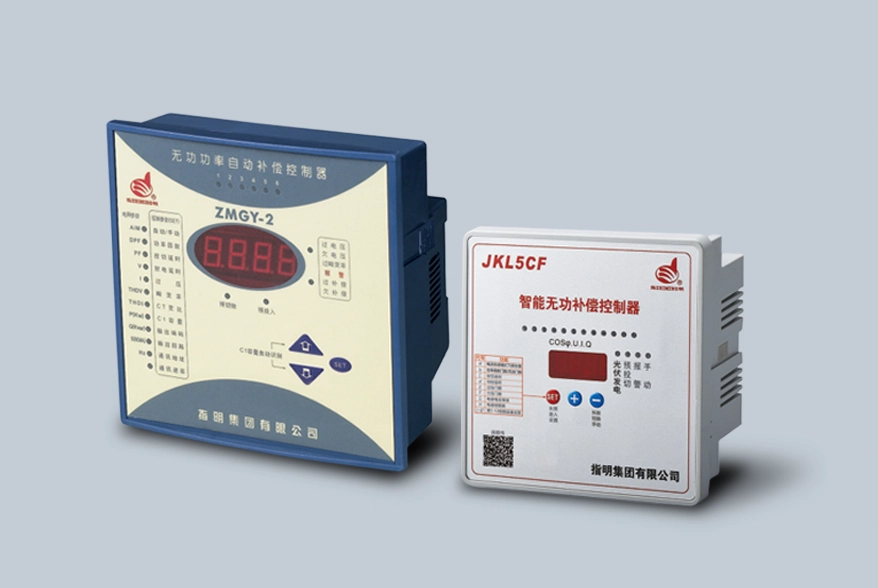
O que faz realmente um controlador de fator de potência
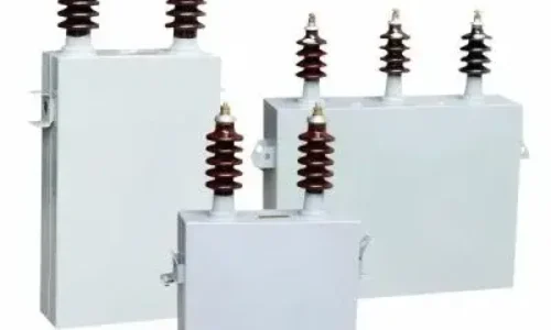
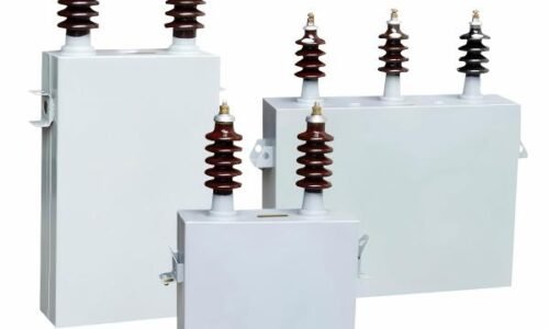
No seu núcleo, um controlador de correção do fator de potência lê a corrente e a tensão do sistema, calcula o fator de potência atual e, em seguida, decide se deve ligar ou desligar as baterias de condensadores do circuito. Os condensadores fornecem potência reactiva principal que compensa a potência reactiva secundária das cargas indutivas. O controlador automatiza este ato de equilíbrio.
A maioria das unidades modernas utiliza uma abordagem faseada - controlam várias fases de condensadores, ligando-os um de cada vez, conforme necessário. A lógica não é apenas “o fator de potência é baixo, adicione condensadores”. É mais complexa do que isso. Um bom controlador considera:
- O fator de potência pretendido (normalmente definido entre 0,95 e 0,99)
- A procura atual de potência reactiva
- Tempos de atraso de comutação para evitar ciclos rápidos de ligar/desligar
- O número de escalões de condensadores disponíveis e as suas dimensões
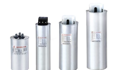
Para instalações comerciais mais pequenas - pense em espaços comerciais, pequenas oficinas ou edifícios comerciais ligeiros - um controlador de condensador de fase dividida lida com sistemas monofásicos ou bifásicos em que a carga reactiva é moderada, mas ainda assim vale a pena corrigir.
Porque é que é importante - O impacto no mundo real
É aqui que se torna tangível. Um fator de potência fraco não aparece apenas como um número abstrato num contador - tem consequências financeiras e operacionais reais.
As penalidades da concessionária são uma penalidade aparente que algumas empresas de eletricidade aplicam se o fator de potência de um local cair abaixo de um limite acordado (geralmente entre 0,90 e 0,95). O custo associado a este facto pode facilmente atingir os milhares de dólares por ano para um local de média dimensão. Além disso, algumas empresas ajustam os seus encargos de procura com base na potência aparente (kVA) e não na potência real (kW), o que significa que um mau fator de potência aumenta a fatura da empresa, mesmo que não exista uma penalização específica referida na tabela de tarifas da empresa.
Seguidamente, a capacidade do sistema. A corrente reactiva existente nos cabos, transformadores e comutadores ocupa algum espaço no seu interior. Ao corrigir o fator de potência para libertar esse espaço, o sistema terá capacidade adicional disponível para possivelmente atrasar ou evitar totalmente uma atualização dispendiosa da infraestrutura. Muitas instalações descobrem que podem instalar novos equipamentos sem ter de aumentar o tamanho dos seus transformadores, utilizando simplesmente a compensação para reduzir a quantidade de carga de potência aparente.
A principal vantagem de um equipamento mais duradouro é o facto de uma corrente mais baixa significar uma carga térmica mais baixa para os condutores e para o equipamento de comutação. Uma vez que há menos calor, obtém-se uma vida mais longa de ambos os componentes. Ao longo de vários anos, isso representa um montante considerável, mas é difícil quantificar o valor real em dólares poupado.
Sectores que mais beneficiam
A compensação de potência reactiva não se limita à indústria pesada, embora seja aí que o impacto é mais dramático. As instalações que tendem a registar os maiores retornos incluem:
- Instalações de fabrico com grandes cargas de motores
- Explorações mineiras e de transformação de minérios
- Instalações de tratamento de água e de águas residuais
- Edifícios comerciais com sistemas AVAC extensos
- Centros de dados (surpreendentemente - os sistemas UPS e as cargas de arrefecimento contribuem)
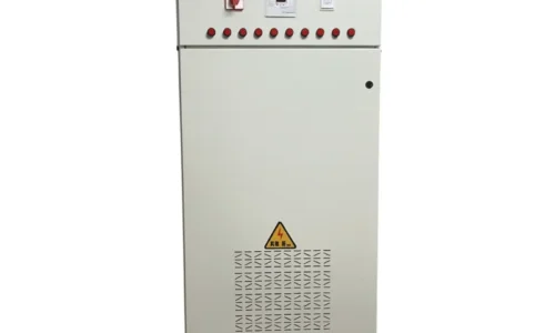
Em ambientes industriais pesados - fábricas com dezenas de motores de indução, fábricas de processamento com grandes conjuntos de compressores - um controlador de condensador trifásico é a escolha padrão, construída para lidar com as exigências reactivas mais elevadas e as sequências de comutação mais complexas que estas instalações requerem.
Principais caraterísticas a procurar num controlador de compensação de potência reactiva
Nem todos os controladores são criados da mesma forma. Ao avaliar as opções, algumas caraterísticas tendem a separar o adequado do genuinamente útil:
- Número de passos de saída - Mais passos significa um controlo mais preciso. Um controlador de 12 passos pode corresponder à carga com mais precisão do que uma unidade de 6 passos.
- Tempo de resposta - A rapidez com que o controlador reage às alterações de carga é importante, especialmente em instalações com uma procura que varia rapidamente.
- Protocolos de comunicação - A conetividade Modbus, RS485 ou Ethernet permite a integração com sistemas SCADA ou de gestão de edifícios.
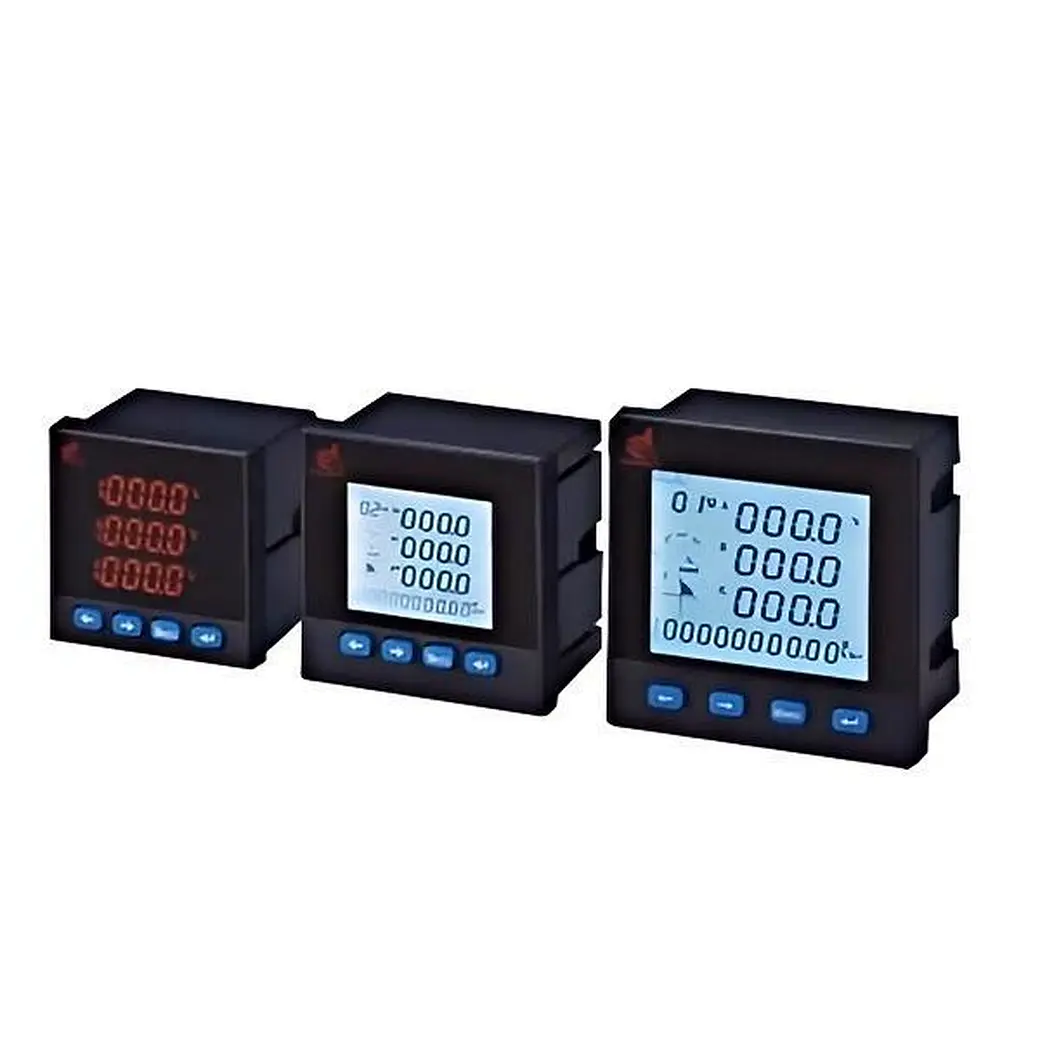
- Ecrã e diagnóstico - Uma interface clara que mostra o fator de potência em tempo real, o estado dos passos e as condições de alarme facilita muito a resolução de problemas.
- Compatibilidade harmónica - Em sistemas com variadores de frequência ou outras cargas não lineares, o controlador deve ser classificado para lidar com a distorção harmónica sem falsas comutações.
Equívocos comuns sobre a correção do fator de potência
Há alguns mitos que tendem a circular e que vale a pena esclarecer.
Reduz a quantidade de energia que utiliza. Não. A correção do fator de potência reduz a procura de energia aparente e reactiva, reduzindo assim o preço da energia e proporcionando poupanças de capacidade. As suas cargas (tal como entregues) consomem aproximadamente o mesmo kWh de eletricidade, qualquer que seja o fator de potência. No entanto, ao evitar penalizações e reduzir as perdas, estará a poupar dinheiro em comparação com a utilização de menos energia da forma “tradicional”.
Os únicos sítios que precisam de grandes geradores são as grandes fábricas. No entanto, as pequenas empresas podem, por vezes, ter um fator de potência bastante baixo se tiverem muitos motores para processar artigos ou comprimir ar. Um exemplo é uma mercearia de tamanho médio que tem muitos frigoríficos. Normalmente, estes fazem muito mais trabalho do que o esperado.
Os condensadores podem ser instalados e depois deixados em paz. Com condensadores fixos a funcionar em condições de estado estacionário, é importante notar que a maioria das cargas reais varia em termos de requisitos de consumo. Se não tiver controlos automáticos, poderá causar uma condição de sobretensão - um fator de potência superior - que pode levar a problemas como o aumento da tensão e outras condições que podem ser piores do que o seu problema original.
FAQ
Pode um controlador do fator de potência coordenar-se tanto com bancos de condensadores fixos como com bancos de condensadores comutados automaticamente?
Sim, a maior parte dos controladores modernos de compensação de potência reactiva são concebidos para trabalhar em conjunto com fases de condensadores fixos. O controlador considera a correção de base fornecida pelos bancos fixos e depois gere os estágios automáticos para lidar com a parte variável da carga reactiva. Esta abordagem híbrida é, de facto, bastante comum em instalações onde uma parte da carga indutiva é constante.
Quais são os riscos se o controlador não tiver passos de condensador suficientes para a carga ligada?
Uma configuração subdimensionada leva a uma correção grosseira - o controlador só pode comutar em grandes blocos de capacitância, que podem ultrapassar ou não o objetivo. Isto resulta na oscilação do fator de potência entre estados sub-compensados e sobre-compensados, causando potencialmente flutuações de tensão e maior desgaste nos contactores de comutação. O dimensionamento correto durante a fase de conceção evita esta situação.
A adoção generalizada de variadores de frequência elimina a necessidade de correção do fator de potência?
Os VFDs melhoram efetivamente o fator de potência de deslocamento dos motores que controlam, o que é um benefício real. No entanto, introduzem correntes harmónicas que distorcem a qualidade geral da energia e podem mesmo piorar o fator de potência de *distorção*. Assim, embora os VFDs ajudem numa dimensão, criam desafios noutra. As instalações com uma utilização intensiva de VFDs continuam frequentemente a necessitar de compensação - por vezes associada a filtragem de harmónicas - para manter uma qualidade de energia aceitável em toda a linha.