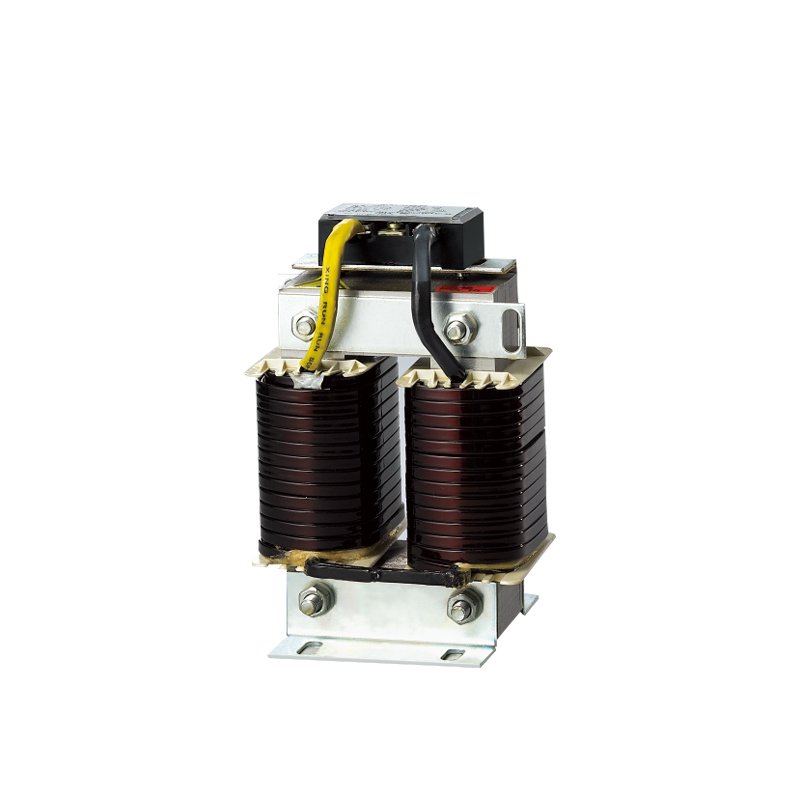
Problema: Bajo factor de potencia (0,65–0,75) debido al uso de motores, transformadores y equipos de soldadura de gran tamaño.
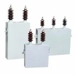
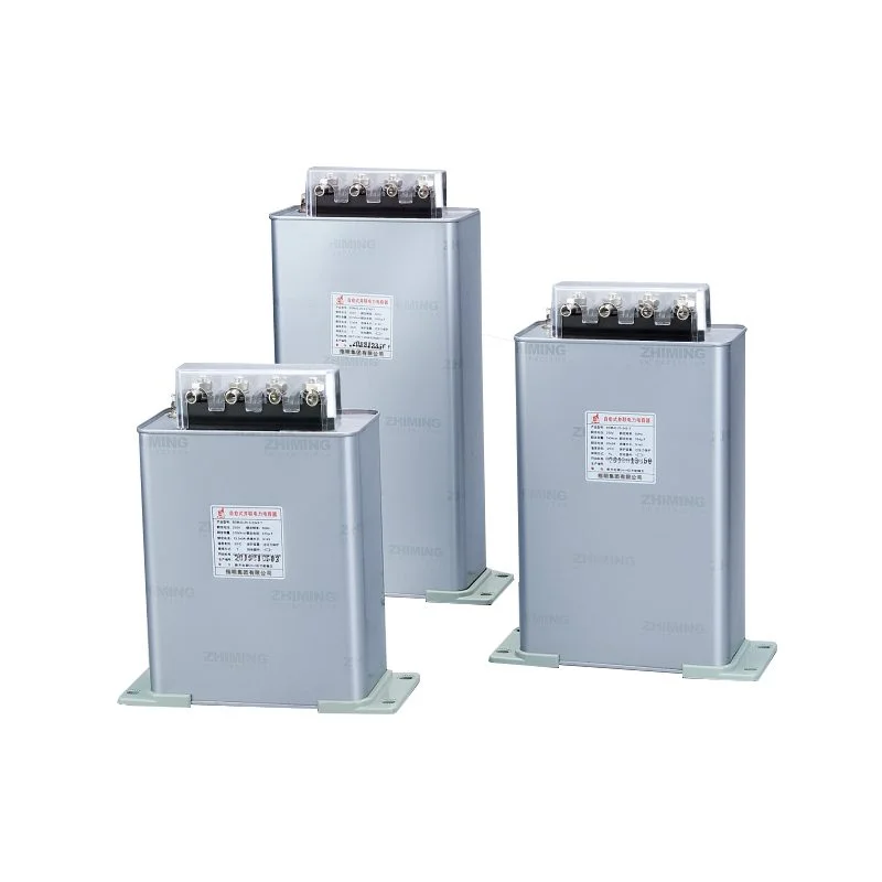
Solución: Instalar bancos de condensadores de baja tensión en los terminales del motor o en el cuadro de distribución principal.
Resultado: PF aumentado a ≥0,96; reducción de la pérdida de energía en un 12–181 TP3T; período de recuperación de la inversión < 8 meses.