Índice
What Is a Current Transformer and Why Does Selection Matter?
A current transformer (CT) is an instrument transformer that produces a reduced current proportional to the current in its primary circuit. In essence, it takes a large primary current—sometimes thousands of amps—and scales it down to a standardized secondary current, typically 1A or 5A, that can be safely measured by meters, relays, and other protection devices.
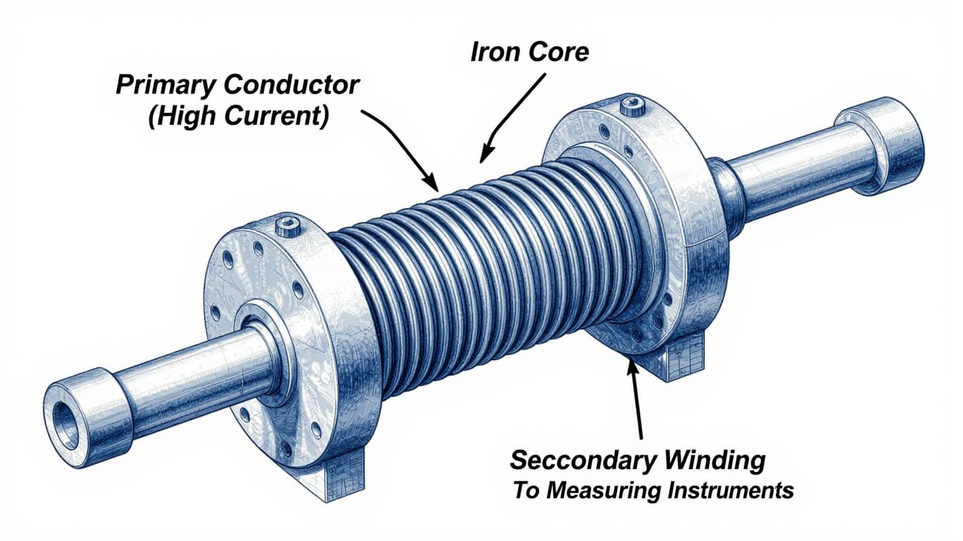
The selection of a current transformer might seem like a straightforward technical decision, but its implications ripple across the entire electrical system. An incorrectly chosen CT can lead to inaccurate energy billing, nuisance tripping of protection relays, or worse—failure to trip during actual fault conditions. In high-power installations, improper selection can cause the CT core to saturate during faults, compromising the operation of protection systems and potentially leading to equipment damage or safety hazards.
Getting the selection right from the start is far more cost-effective than troubleshooting metering discrepancies or relay misoperations after installation. So, where does one begin?
Key Parameters for Current Transformer Selection
Rated Primary Current – Getting the Ratio Right
The rated primary current is arguably the most fundamental parameter in CT selection. It determines the ratio at which the CT transforms the primary current to the secondary current—for instance, a 600/5A CT transforms 600 amperes on the primary side to 5 amperes on the secondary side.
Standardized rated primary currents follow a preferred number series: 10, 12.5, 15, 20, 25, 30, 40, 50, 60, 75A, along with their decimal multiples. The goal is to select a ratio that places the expected operating current in the optimal range for the CT’s accuracy.
A practical rule of thumb: select a primary current rating slightly above the expected maximum operating current—typically around 1.1 to 1.2 times the normal full-load current. For motor applications, multiplying the full-load amperes by 1.25 is a common approach that places the operating current above two-thirds of the CT’s full scale while providing headroom for overload conditions.
However, there’s a catch. Overdimensioning—choosing a CT with a primary rating far exceeding the actual load—must be avoided. When a CT is oversized, the measuring accuracy at relatively low currents (in relation to the primary rated current) can be considerably reduced. For metering applications specifically, the primary current should not exceed 1.5 times the maximum operating current to maintain accuracy within the rated range.
For those seeking a reliable transformador de corriente solution, understanding these ratio fundamentals is the essential first step.
Secondary Current – 1A or 5A?
The secondary current rating—either 1A or 5A—might seem like a minor detail, but it has significant practical implications.
Most measurement devices offer higher accuracy at 5A, which is why 5A secondary CTs remain the most frequently used option. However, for installations where the CT is located a considerable distance from the metering or protection equipment, 1A secondary CTs offer a compelling advantage: line losses for 1A transformers are only 4% compared to 5A transformers.
This difference becomes critical when long cable runs are involved. The voltage drop (and consequent burden) across the secondary leads is proportional to the square of the current—so reducing the secondary current from 5A to 1A dramatically reduces the burden imposed by the wiring. The trade-off? Measurement devices for 1A secondary circuits often have slightly lower measuring accuracy.
The decision between 1A and 5A ultimately depends on the distance between the CT and the connected devices, as well as the existing equipment’s compatibility.
Accuracy Class – Metering vs. Protection
Accuracy classes are where many selection processes go wrong. The class designation directly corresponds to the maximum permissible error in current measurement, but metering and protection applications have fundamentally different accuracy requirements.
For metering applications (energy accounting, billing, load profiling), standard accuracy classes include 0.1, 0.2, 0.5, 1, 3, and 5. The number represents the percentage error at rated current—so a 0.2 class CT has a maximum error of ±0.2% at rated current. S-class CTs (0.2S, 0.5S) offer extended accuracy down to 1% of rated current, making them particularly suitable for applications where loads vary widely.
For protection applications (overcurrent relays, differential protection), accuracy classes use a different notation: 5P10, 5P20, 10P10, and so on. The “P” stands for protection, the number before “P” indicates the percentage composite error at the rated accuracy limit primary current (5% for 5P, 10% for 10P), and the number after “P” is the accuracy limit factor—the multiple of rated primary current at which the specified accuracy is guaranteed.
For example, a 5P20 CT will maintain a composite error of less than 5% at up to 20 times its rated primary current. This ensures the CT can accurately reproduce fault currents for protection relays during short-circuit conditions.
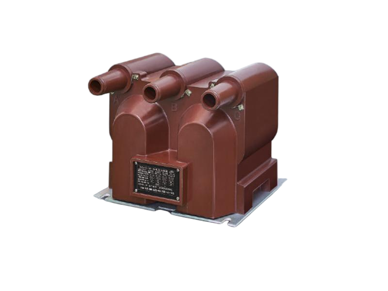
A High Voltage Current Transformer for protection applications must be specified with the appropriate protection class to ensure reliable operation during fault conditions.
Burden (VA) – Don’t Underestimate the Load
Burden is the total load that a current transformer must drive on its secondary side, expressed in volt-amperes (VA). It encompasses three components:
- The power consumption of all connected devices (meters, relays, transducers)
- The resistance of the secondary leads (wiring between CT and devices)
- The internal resistance of the CT’s secondary winding
Calculating burden accurately is where many specifications fall short. Standardized rated burdens are 2.5, 5, 10, 15, and 30VA, though higher values may be selected depending on the application.
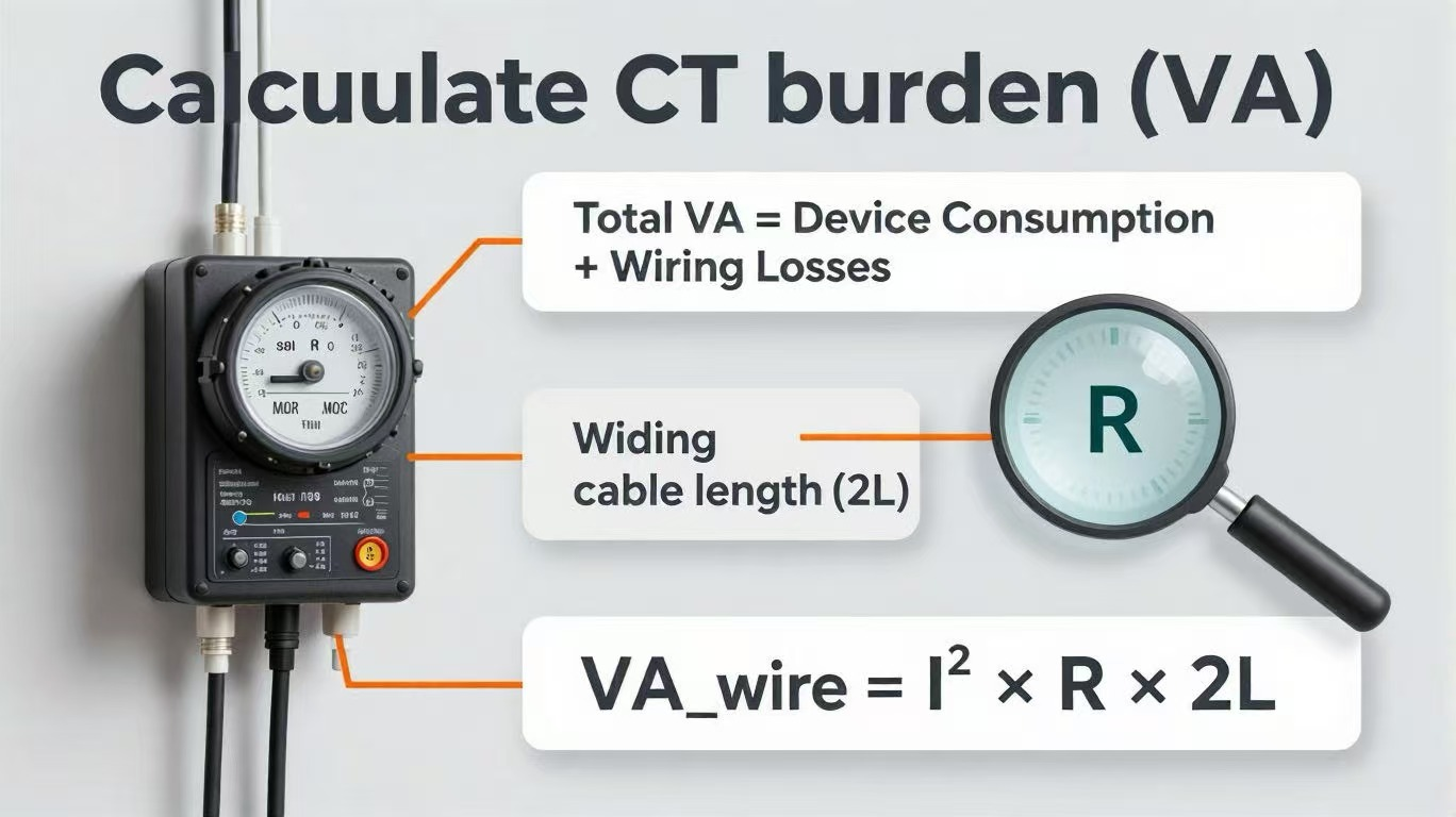
The basic burden calculation follows Ohm’s law: VA = I² × R, where I is the secondary current and R is the total resistance of the circuit. For the wiring component specifically, the formula expands to VA = I² × R × 2L, where L is the cable length (the factor of 2 accounts for the complete circuit loop).
Why burden matters: If the connected burden is too low (underloading), the overcurrent factor increases, and measurement devices may not be adequately protected during short circuits. If the burden is too high (overloading), accuracy suffers. Most multifunction and digital meters have a burden of less than 0.2VA, while analog meters tend to be less than 0.75VA—but the wiring can easily dominate the total burden in installations with long cable runs.
A Transformador de corriente de baja tensión should be selected with a burden rating that comfortably exceeds the calculated total connected load, typically with a safety margin of 20-50%.
Types of Current Transformers – Which One Fits Your Installation?
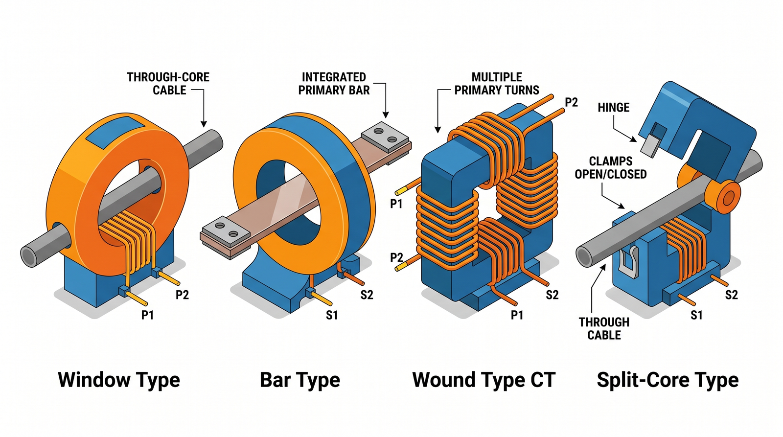
Current transformers come in several physical configurations, each suited to different installation scenarios.
| Tipo | Descripción | Ideal para | Consideraciones sobre la instalación |
|---|---|---|---|
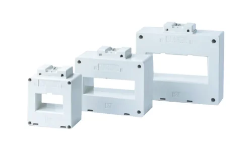
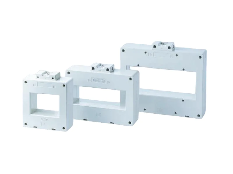
| Window-Type (Through-Core) | Circular opening in the core; primary conductor passes through the window | New installations where the primary conductor can be threaded through | Requires disconnection of the primary circuit for installation |
| Bar-Type | Primary is a straight bar (single turn) passing through the CT core window | Busbar applications and high-current measurements | The bar is permanently integrated; no separate primary winding |
| Wound-Type | Primary winding consists of multiple turns | Low-current applications where a higher turns ratio is needed | More expensive; offers higher accuracy at lower currents |
| Split-Core | Core can be opened for installation around existing conductors without disconnecting circuits | Retrofit applications and temporary installations | Only suitable for insulated conductors in dry locations |
The choice between these types often comes down to whether the installation is new or a retrofit. Split-core CTs have revolutionized retrofit applications by eliminating the need to disconnect primary conductors. However, solid-core CTs generally offer higher accuracy and are preferred for permanent installations where maximum precision is required.
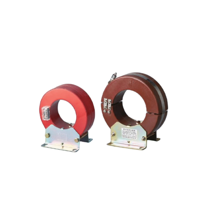
For specialized applications like ground fault protection, a Transformador de corriente de secuencia cero is specifically designed to detect residual currents by encircling all three phases and the neutral conductor simultaneously.
Environmental and Installation Considerations
The physical environment plays a substantial role in CT selection—a factor that is surprisingly easy to overlook.
Indoor vs. Outdoor: Indoor switchgear typically uses compact epoxy-resin encapsulated CTs, while outdoor applications may require oil-immersed designs for 11kV/33kV grids or SF₆ gas-insulated types for extreme conditions.
Temperature and Humidity: Most CTs are rated for ambient temperatures between -25°C and +40°C. Operation outside this range may require special designs or derating. High humidity or corrosive environments demand additional protection—epoxy resin casting offers excellent moisture resistance, while oil-immersed CTs may be preferred in polluted environments.
Insulation Level: The required insulation level depends on the system voltage and installation category. For medium-voltage applications (6kV–36kV), compact epoxy-resin encapsulated CTs are common. High-voltage applications demand more robust insulation systems with appropriate Basic Impulse Level (BIL) ratings.
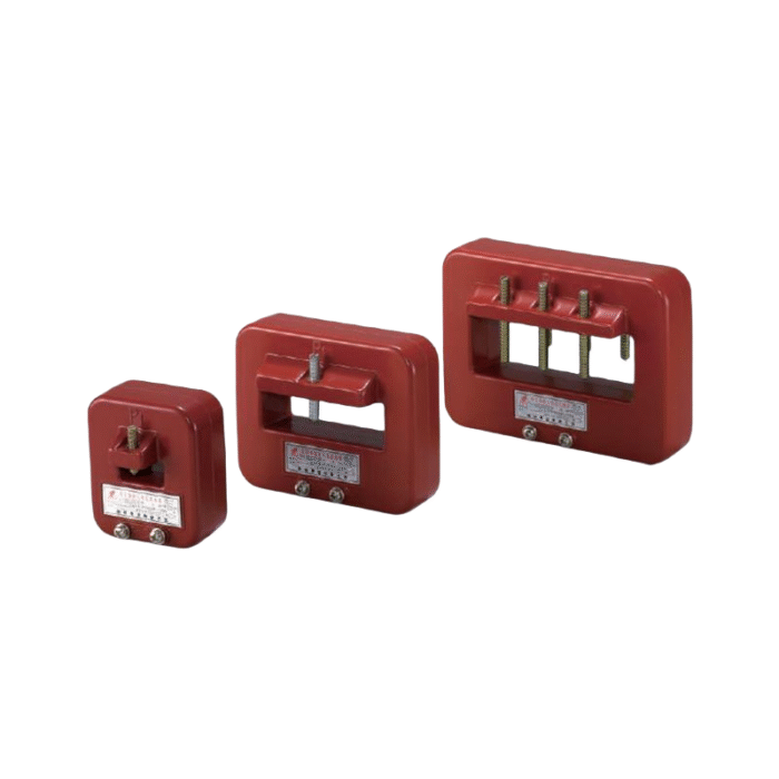
Physical Space: The CT’s physical dimensions—particularly the window opening—must accommodate the primary conductor or busbar. A general guideline is that the inner diameter of the CT should be sized to be no more than twice the diameter of the load cable.
Common Mistakes to Avoid When Selecting a CT
Even experienced engineers can fall into these traps:
Mistake 1: Confusing metering and protection accuracy classes. A 0.5 class CT is excellent for billing but may saturate during faults. A 5P20 CT is designed for fault conditions but lacks the precision for revenue metering. These are not interchangeable.
Mistake 2: Miscalculating burden by omission. Many specifications account for the meter’s burden but ignore the wiring. With long cable runs, the wiring burden can easily exceed the meter’s consumption. The total burden—devices plus wiring—must be calculated.
Mistake 3: Oversizing the primary current rating. It’s tempting to select a larger CT “just to be safe.” But a CT that is too large will operate at a small fraction of its rated current, where accuracy is poorest. Select the smallest standard rating that comfortably accommodates the maximum operating current.
Mistake 4: Ignoring the Instrument Security Factor (ISF) for metering CTs. ISF ensures that the secondary current does not rise dangerously during primary overcurrent conditions. An ISF of 5 means that at 5 times rated primary current, the composite error exceeds 10%—the CT saturates to protect connected instruments. An ISF of 10 or higher may allow excessive current to reach the meter, causing damage.
Mistake 5: Opening the secondary circuit while the CT is energized. This cannot be emphasized enough: never, ever disconnect a current transformer’s secondary while the primary is live. The secondary winding will attempt to drive its current into an open circuit, potentially generating dangerously high voltages.
Current Transformer Selection Checklist
A systematic approach reduces the risk of oversight:
- Define the application – Is this for metering, protection, or both? This determines the accuracy class and core type.
- Determine the maximum operating current – Calculate the expected full-load current and add an appropriate margin (typically 1.1–1.25×).
- Select the primary current rating – Choose the nearest standard rating above the calculated value.
- Choose the secondary current – 5A for short distances and maximum device accuracy; 1A for long cable runs.
- Specify the accuracy class – 0.2S or 0.5S for precision metering; 5P10 or 5P20 for protection.
- Calculate the total burden – Sum the consumption of all connected devices plus the wiring losses.
- Select the VA rating – Choose a standard VA rating above the calculated burden.
- Verify physical fit – Confirm the CT’s window or form factor accommodates the primary conductor.
- Check environmental suitability – Confirm the CT’s insulation, temperature rating, and ingress protection match the installation environment.
- Confirm standard compliance – Ensure the CT meets applicable standards such as IEC 61869 or IEEE C57.13.
Conclusión
Selecting the right current transformer is a balancing act—between accuracy and robustness, between immediate needs and future flexibility, between cost and performance. The process demands attention to the application’s specific requirements: metering demands precision at normal operating currents; protection demands fidelity under fault conditions; and the installation environment demands appropriate physical and electrical characteristics.
The most common selection errors—oversizing the primary rating, miscalculating burden, or confusing metering and protection classes—are all avoidable with a systematic approach. Start with the application, work through each parameter methodically, and verify the selection against the installation’s physical and environmental constraints.
A well-chosen current transformer will provide years of reliable service, accurate measurements, and dependable protection. A poorly chosen one will generate headaches—inaccurate bills, nuisance trips, or worse, undetected faults. The extra time invested in proper selection is repaid many times over in operational reliability.
For a comprehensive range of current transformers across various voltage levels and applications—from low-voltage metering to high-voltage protection—explore the full current transformer product portfolio.
Preguntas frecuentes
What is the practical difference between metering and protection current transformers, and can one CT serve both purposes?
Metering CTs are optimized for accuracy at normal operating currents and are designed to saturate at relatively low overcurrent levels (typically 5–10 times rated current) to protect connected instruments. Protection CTs, by contrast, are designed to remain accurate at much higher multiples of rated current (typically 10–30 times) to faithfully reproduce fault currents for relay operation. While multi-core CTs with separate metering and protection windings are available, a single CT core cannot optimally serve both purposes—the design requirements are fundamentally contradictory. For applications requiring both functions, specify a CT with dual cores: one metering-grade core and one protection-grade core.
How can I determine whether my existing CT has sufficient burden capacity when adding new monitoring equipment?
First, identify the existing CT’s rated burden from its nameplate (expressed in VA). Then, calculate the total burden of all devices currently connected, plus the burden of the wiring. Add the burden of the proposed new equipment (consult the manufacturer’s specifications). If the sum exceeds the CT’s rated burden, accuracy will be compromised. In practice, most digital meters have very low burden (often below 0.2VA), so adding one or two devices may be acceptable. However, long cable runs can quickly consume the available burden capacity. If the calculated burden approaches the CT’s rating, consider installing a burden-reducing device or replacing the CT with a higher VA rating.
Can a window-type CT be used for zero sequence (ground fault) protection?
A single window-type CT encircling all three phase conductors can be used for zero sequence protection—this is precisely the configuration of a zero sequence CT. The CT measures the vector sum of the three-phase currents, which should be zero under balanced conditions. Any residual current indicates a ground fault. However, for this application, the CT must have sufficient sensitivity at low currents (typically a few amperes) and must be rated for the system voltage. Standard window-type CTs for metering or general protection may not have the required low-current accuracy or insulation rating for ground fault detection. A dedicated zero sequence current transformer is specifically designed with the sensitivity and construction required for reliable ground fault protection.