Most electrical systems don’t operate at unity power factor. That’s just the reality. Inductive loads — motors, transformers, fluorescent lighting — pull reactive power from the supply, dragging the power factor down. The result is higher current, more losses, and often a bigger electricity bill than necessary.
Making corrección del factor de potencia work isn’t overly complicated, but it does require some understanding of the system, the loads involved, and the right equipment for the job. It’s one of those things that seems straightforward on paper but has a few nuances in practice that are easy to overlook.
Índice
Understanding the Need for Power Factor Correction
Before installing anything, it helps to understand what’s actually happening. When the power factor is low (say, 0.7 or 0.75), a significant portion of the current flowing through the system is doing no useful work. It’s just cycling back and forth between the source and the load, heating up cables and taking up transformer capacity along the way. A transformador de corriente de baja tensión installed on the main feeder will faithfully register this inflated current magnitude, even though much of what it measures represents wasted reactive energy rather than actual kilowatts delivered.
Utilities notice this. Many of them impose reactive power charges or power factor penalties once it drops below a threshold — typically around 0.9 or 0.95 depending on the region. So there’s a direct financial incentive to correct it, beyond just the technical benefits.
Steps to Make Power Factor Correction Effective
Step 1 — Measure the Existing Power Factor
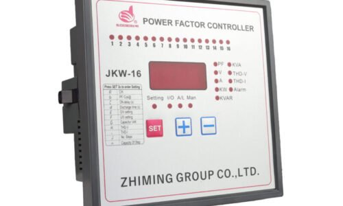
This is where everything starts. Without accurate measurements, any correction effort is basically guesswork. A power quality analyzer or even a simple clamp meter with power factor reading capability can provide baseline data.
Key things to measure:
Active power (kW)
Reactive power (kVAR)
Apparent power (kVA)
Current power factor (lagging or leading)
Step 2 — Determine the Required Correction
Once the existing power factor is known, the target power factor needs to be set. Most facilities aim for something between 0.95 and 0.99. From there, the required reactive power compensation can be calculated.
The formula is fairly standard:
Required kVAR = kW × (tan φ₁ − tan φ₂)
Where φ₁ is the angle corresponding to the existing power factor and φ₂ corresponds to the target.
Step 3 — Select the Correction Equipment
This is where choices come in. The most common options include:
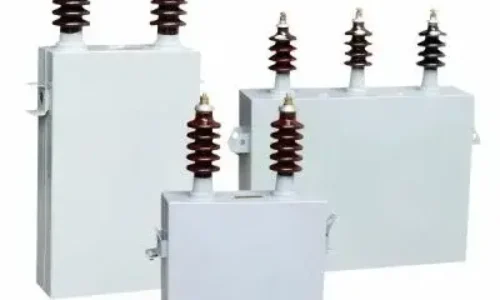
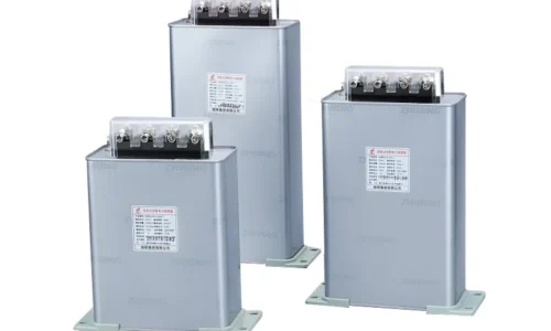
Fixed capacitor banks — suitable for constant loads
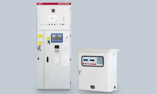
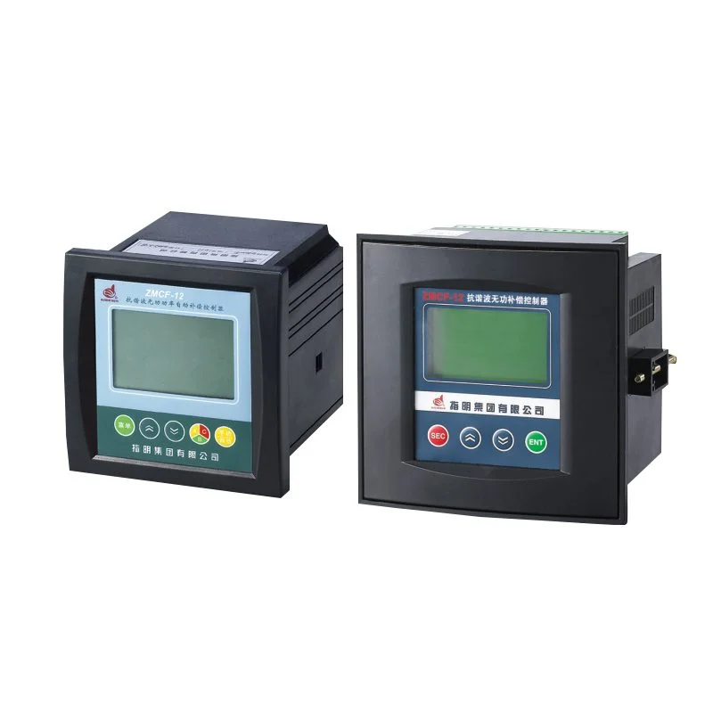
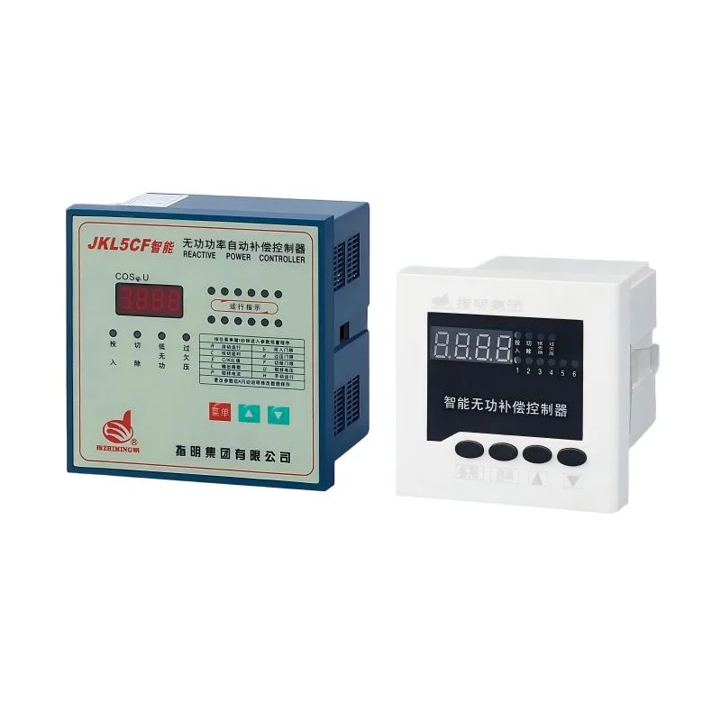
Automatic power factor correction (APFC) panels — for variable loads
Detuned reactors with capacitors — for systems with harmonic distortion
Active harmonic filters — for complex, non-linear load environments
Each has its place. For a facility with steady motor loads running around the clock, fixed capacitors might be perfectly adequate. But for something like a manufacturing plant where loads change throughout the day, an APFC panel with multiple capacitor stages makes a lot more sense.
Step 4 — Install and Commission
Installation location matters more than people sometimes realize. Power factor correction equipment can be installed at:
The main incoming supply (centralized correction)
Distribution boards (group correction)
Individual motor terminals (local correction)
Centralized correction is simpler and cheaper to maintain but doesn’t reduce losses within the internal distribution network. Local correction at each motor eliminates internal losses but costs more upfront. Group correction sits somewhere in between — a reasonable compromise for many setups.
Common Mistakes in Power Factor Correction
Even with good intentions, things can go sideways. A few issues that come up regularly:
Over-correction leading to a leading power factor, which some utilities also penalize
Installing capacitors on systems with high harmonic content without detuning reactors — this can cause resonance and even capacitor failure
Ignoring the switching transients that occur when capacitor stages engage
Not accounting for future load changes, leaving the system under-corrected within a year or two
It’s the kind of thing where a bit of upfront analysis saves a lot of headaches later. Rushing into a solution without proper measurement data almost always leads to suboptimal results.
Preguntas frecuentes
How long does it take for power factor correction to pay for itself?
In most cases, the payback period is between 12 and 24 months. Facilities with heavy reactive power penalties often see returns even faster. The exact timeline depends on the utility rate structure and the size of the correction system installed.
Can power factor correction damage equipment?
If done improperly, yes. Capacitors installed on systems with significant harmonic distortion can experience overheating or resonance. That’s why harmonic analysis should be part of the assessment before any correction equipment is selected.
Does power factor correction reduce actual energy consumption?
Not directly — it reduces reactive power, not active power. However, by lowering the total current in the system, it reduces I²R losses in cables and transformers. So there is a small but real reduction in energy wasted as heat, plus the financial savings from avoided penalties.