Industrial facilities, commercial complexes, and infrastructure projects frequently run into a common, expensive headache: power quality issues. Whether it manifests as a sudden spike in utility bills due to low power factor penalties, or unexplained equipment overheating, the root of the problem often traces back to how reactive power is managed within the facility. When engineering teams realize they need to stabilize their electrical network, the initial response is usually to purchase a corrective device. However, selecting the ideal power capacitor is rarely a matter of picking a standard model off a shelf based on a single horsepower or kilowatt rating.
A distribution network is a living, fluctuating environment. Choosing the wrong equipment can lead to premature component failure, systemic resonance, or worse, absolute electrical failure. Making an informed decision requires looking deep into the electrical grid’s specific layout, calculating precise displacement demands, and factoring in the unseen variables like harmonic distortion that quietly destroy modern industrial hardware.
Mục lục
1. Demystifying Grid Requirements: The First Step in Power Capacitor Selection
Before looking at a manufacturer’s catalog, one has to audit the electrical environment where the equipment will reside. A common mistake is analyzing the facility’s load profile as if it exists in a vacuum, ignoring the broad grid architecture it connects to. The grid’s nominal voltage, configuration, and the nature of the connected machinery dictate the foundational boundary lines for your equipment selection.
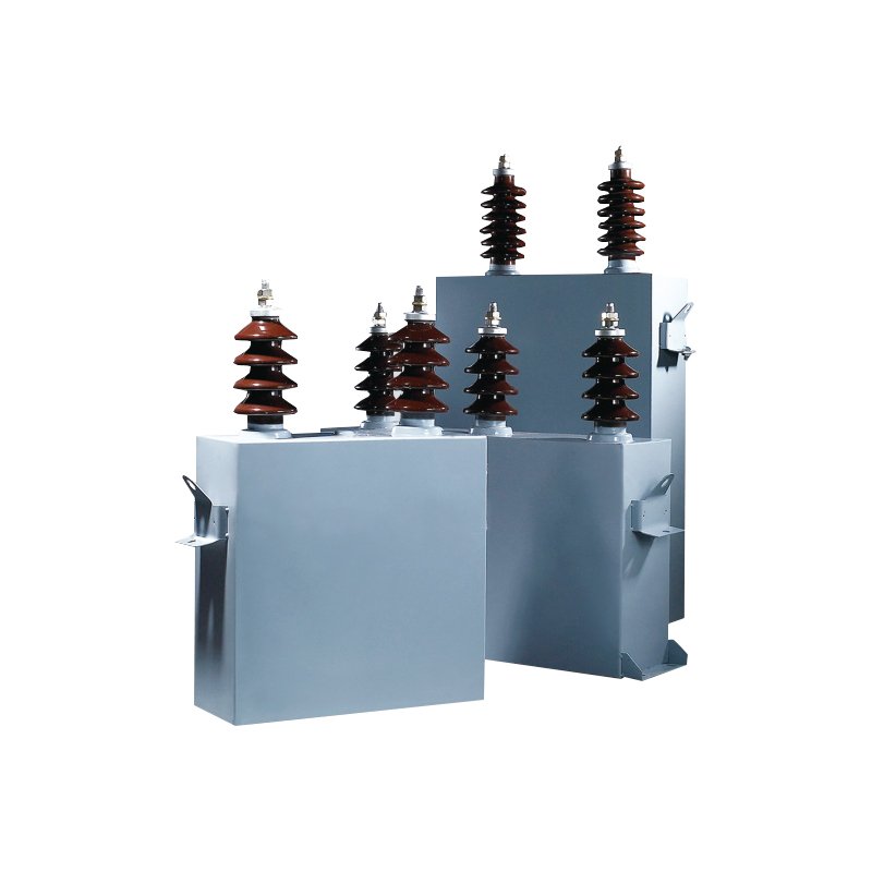
High-Voltage Ingress: For heavy industrial manufacturing zones, chemical processing plants, or regional substations where the main supply comes directly from transmission infrastructure, standard components will instantly fail under the massive dielectric stress. These environments demand a ruggedized, heavily insulated tụ điện cao áp capable of handling kilovolt-level tensions and large structural surges without suffering dielectric breakdown.
Low-Voltage Distribution: Conversely, inside typical commercial buildings, small-to-medium assembly plants, or standard motor control centers (MCCs), the system voltage generally stays well below 1,000 volts. In these scenarios, a standard industrial tụ điện nguồn điện áp thấp provides the exact reactive compensation needed to optimize the power factor without introducing unnecessary equipment costs or extreme insulation profiles.
Characterizing Your Electrical Loads
It helps to categorize the equipment drawing power from your system. Linear loads, such as standard three-phase induction motors, incandescent lighting, and standard resistance heaters, draw current that mimics the sinusoidal shape of the voltage wave. Compensating for these loads is straightforward.
However, modern plants are filled with non-linear loads. Variable frequency drives (VFDs), soft starters, LED lighting banks, and welding machines draw current in abrupt, short pulses. This pulsed demand distorts the voltage waveform, creating harmonics. If your facility is dominated by non-linear loads, picking a basic capacitor bank without checking the harmonic profile will lead to severe overcurrent conditions.
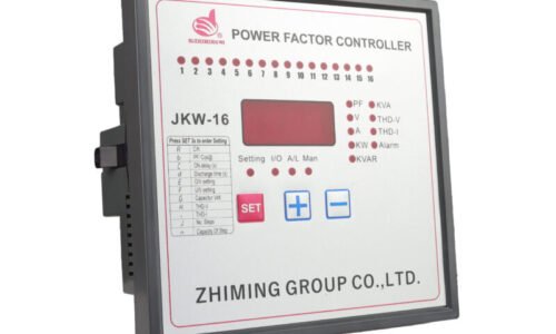
To keep track of how these fluctuating loads alter the network’s behavior in real time, intelligent control systems rely on data from a Biến dòng installed at the main incoming breaker. This monitoring device scales down high operational currents to a safe, measurable signal, allowing power factor controllers to accurately calculate how much capacitance needs to be switched in or out to maintain the target efficiency.
2. Key Technical Parameters You Cannot Afford to Ignore
Once the grid layout is defined, the selection process moves to technical specifications. Looking at a nameplate requires reading between the lines; a unit’s rated capacity is only valid under highly specific environmental and electrical states.
Reactive Power Capacity
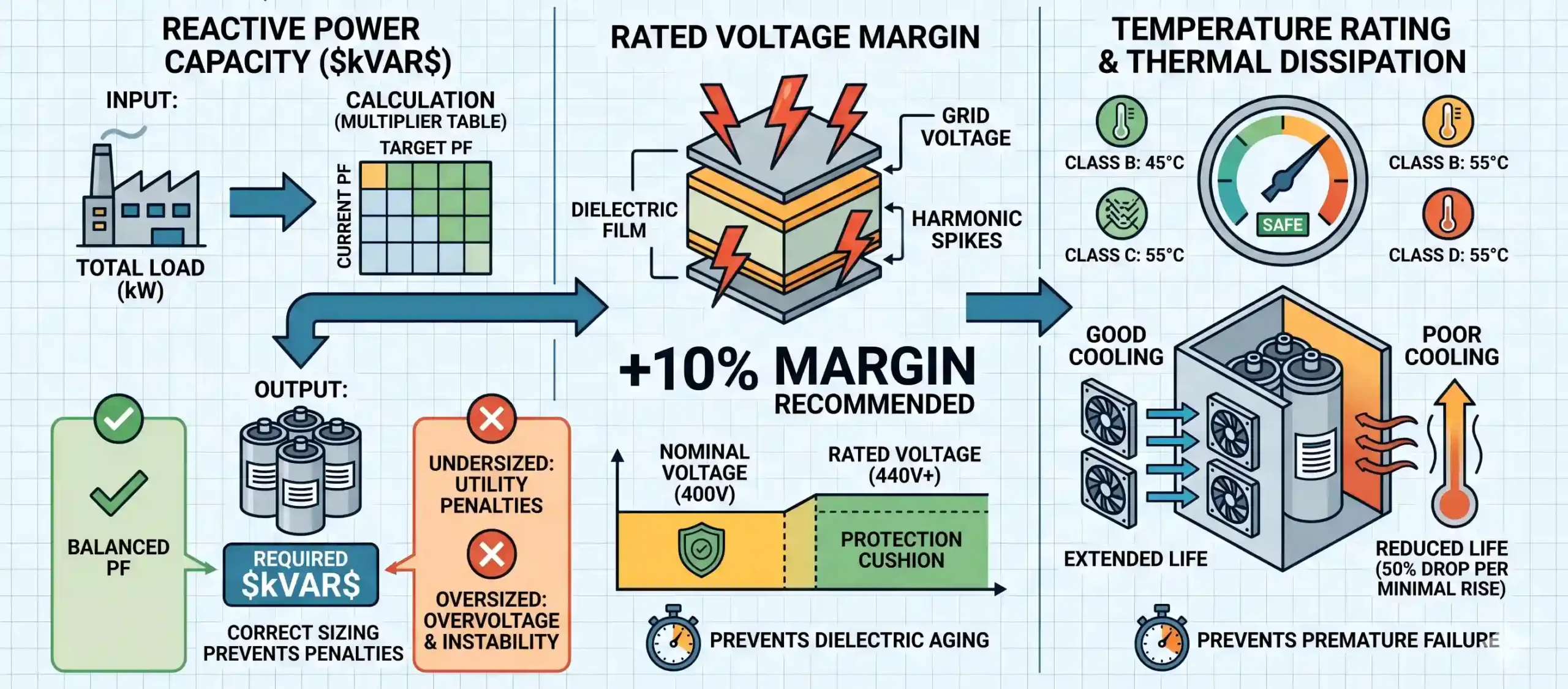
The sizing of a capacitor bank is measured in kilovolt-amperes reactive (kVAR). This value represents the amount of reactive power the unit can inject into the network to counteract the lagging reactive current drawn by inductive loads. To find the correct capacity without relying on mathematical formulas, engineers typically utilize a standard power factor correction multiplier table. By crossing your current power factor value with your desired target value (usually set between 0.95 and 0.98), you get a single multiplier coefficient. Multiplying this coefficient by your facility’s peak operational kilowatt load gives you the exact capacity requirements.
Undersizing the system means you will continue to pay power factor penalties to the utility provider. Conversely, oversizing the system results in an overcorrected, leading power factor. This condition can trigger dangerous overvoltages, cause voltage instability, and confuse building automation systems.
Rated Voltage Margin
A capacitor’s insulation layer degrades exponentially faster when exposed to voltages above its design threshold. Because industrial grids experience routine voltage spikes, transient surges, and harmonic voltage distortion, a professional rule of thumb is to select a unit with a rated voltage at least ten percent higher than the actual nominal system voltage. For example, in a standard 400-volt system heavily saturated with electronic drives, opting for a unit rated at 440 volts or 480 volts provides a safety cushion that protects the internal dielectric film from premature aging and sudden puncture.
Temperature Rating and Thermal Dissipation
Capacitors generate internal heat during regular operation due to internal resistance within the foil and dielectric film. Ambient temperature classifications—such as Class B (up to 45°C) or Class D (up to 55°C)—indicate the maximum thermal exposure the unit can handle over a 24-hour cycle. If an enclosure lacks active cooling fans or relies on tightly packed components, the internal ambient temperature will quickly skyrocket, cutting the component’s operational life in half for every minimal temperature increase beyond its thermal rating.
| Selection Parameter | Standard Industrial Values | Risk of Inappropriate Selection | Engineering Recommendation |
|---|---|---|---|
| Reactive Capacity (kVAR) | 5 kVAR to 100+ kVAR per ste | Undersizing leads to ongoing utility penalties; oversizing causes overcorrection and system overvoltage. | Use precise billing history and maximum demand kilowatt charts to compute target displacement. |
| Rated Voltage (V_n) | 230V, 400V, 440V, 690V, 6.6kV | Selecting exactly nominal voltage leaves no safety margin for routine grid voltage transients. | Specify a voltage rating minimum ten percent above the measured peak-load network voltage. |
| Harmonic Tolerance | 1.3 times nominal current up to 2.0 times nominal | Unprotected units run into parallel resonance, leading to overheating and casing rupture. | Integrate detuned reactors if non-linear loads exceed twenty percent of the total facility demand. |
| Enclosure IP Rating | IP20 (Indoor) to IP55 (Outdoor) | Dust and moisture ingress cause terminal tracking, flashovers, and external short circuits. | Match enclosure ratings directly to environmental dust, humidity, and corrosive profiles. |
3. Tuning and Protection: Dealing with the Enemy Called Harmonics
In the modern power distribution landscape, harmonic currents pose the greatest threat to capacitor longevity. Because a capacitor’s internal opposition to current drops significantly as the frequency of the electrical system climbs, high-frequency harmonic currents pass through the unit with extreme ease. This characteristic can create a dangerous condition known as electrical resonance.
The Resonance Trap
When a capacitor bank is introduced to a network containing harmonic-producing loads, the combination of the system’s inductive properties (from transformers and motors) and the capacitor’s capacitive properties can form a resonant circuit. If the resonant frequency of this combination aligns with a dominant harmonic frequency generated by the facility’s variable frequency drives, the harmonic currents are amplified many times over. The result is intense overcurrent, severe voltage distortion, loud humming from distribution panels, and rapid equipment destruction.
Selecting the Right Protection Strategy
To avoid resonance, engineers must choose between a standard configuration and a detuned configuration:
Standard Capacitors: Safe to use only if non-linear loads make up less than fifteen to twenty percent of the total building load.
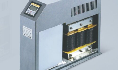
Detuned Capacitor Systems: Essential if non-linear loads exceed twenty percent. In this setup, a heavy iron-core reactor (inductor) is connected in series with the capacitor canister. This reactor changes the resonant frequency of the combination to a point well below the lowest dominant harmonic frequency, protecting the system from resonance.
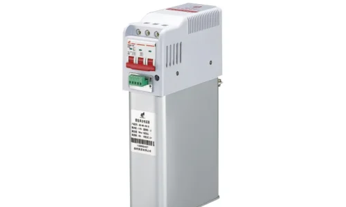
Additionally, how the units are switched in response to changing loads matters. Using mechanical contactors on a rapidly fluctuating load creates heavy inrush currents and voltage spikes. For systems requiring smooth, high-frequency switching, installing a dedicated, fast-acting Tụ điện nguồn switching device or a solid-state thyristor switch ensures the steps engage safely at the exact zero-crossing point of the voltage wave, protecting both the capacitor and nearby sensitive electronics.
To ensure your system architecture aligns with international safety boundaries, engineers often reference the strict harmonic limits outlined by bodies like the Institute of Electrical and Electronics Engineers (IEEE). Adhering to these standards ensures your equipment selection does not inject destructive noise back into the public utility grid.
4. Physical Construction and Environmental Adaptability
The internal chemistry and external physical construction of the capacitor are just as important as its electrical numbers. The environment of a facility—whether it is a clean, air-conditioned data center or a dusty, vibrating cement factory—dictates the physical design requirements of the unit.
Dry-Type vs. Oil-Impregnated Design
The choice of internal insulation material impacts both environmental safety and physical orientation options:
Oil-Impregnated Capacitors: These traditional units use a biodegradable synthetic oil to fill the spaces between the dielectric film sheets. The liquid fill provides excellent heat dissipation and high insulation reliability. However, they carry a small risk of leaking fluid if the outer casing becomes dented, corroded, or over-pressurized, requiring horizontal or vertical mounting restrictions.
Dry-Type Capacitors: These modern units use a solid gas insulation medium or a specialized polyurethane resin fill. They are completely leak-proof, can be mounted in any orientation (even upside down if space is tight), and eliminate the risk of oil-related environmental contamination or fires. This makes them the preferred choice for food processing facilities, commercial office buildings, and marine applications.
Casing Integrity and Terminal Protection
The physical environment dictates the required Ingress Protection (IP) rating for the external housing. Standard indoor applications inside clean electrical rooms typically use IP20 modular canisters with finger-safe terminal blocks.
If your installation sits on an open plant floor subject to conductive metallic dust, fine chemical mist, or high ambient humidity, the terminals must be housed inside an IP54 or IP55 dust-proof and water-resistant enclosure. Exposed terminals in a dirty environment will experience surface tracking, where dust forms a conductive path between the phases, leading to catastrophic terminal flashovers.
5. Conclusion & The Cost of a Wrong Selection
Engineering an efficient power distribution network requires careful attention to detail. Selecting a power capacitor cannot be simplified into a quick transaction based on a generic capacity estimate. It demands an evaluation of system voltage tolerances, thermal limitations, load profiles, and the harmonic profile of the facility’s power grid.
Cutting corners during the audit and selection phase often leads to expensive consequences later. An incorrectly specified unit will run hot, degrade prematurely, and can amplify harmonic resonance, risking sudden equipment failure or damage to adjacent panel electronics.
Conversely, taking a systematic selection approach—calculating true reactive requirements via multiplier charts, including a ten percent voltage safety buffer, selecting detuned reactors when harmonics are present, and matching the physical enclosure to the operating environment—creates an efficient, reliable power system. This up-front investment protects your infrastructure, eliminates low power factor penalties, and extends the operational lifespan of your entire power network.
Câu hỏi thường gặp
How do I determine my facility's base target reactive demand when choosing a new Power Capacitor bank?
The most reliable method is to audit at least twelve months of consecutive utility billing records. Look for the maximum active power demand recorded in kilowatts and the associated monthly average power factor. If your utility bill only states total consumption ratios, you can use industry-standard factor tables. By checking where your current average power factor meets your target goal (typically 0.95 or higher), you will find a direct coefficient. Multiplying this number by your maximum demand kilowatts yields the exact reactive size needed to avoid penalties.
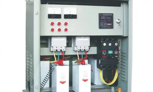
What is the operational difference between fixed and automatic Power Capacitor banks?
A fixed bank stays connected to the network continuously, regardless of the factory’s real-time load profile. This design is ideal for isolating and compensating a single, large inductive machine, like a major wastewater pump, by wiring the unit directly to the motor’s starter switchgear.
An automatic bank uses an electronic controller connected to a current monitoring loop. The controller automatically steps modular blocks of capacitance in and out of the circuit as the facility’s overall load shifts throughout the day. This dynamic adjustment prevents overcorrection during low-load periods, such as nights or weekends, protecting sensitive building electronics from leading power factor overvoltages.
What is the operational difference between fixed and automatic Power Capacitor banks?
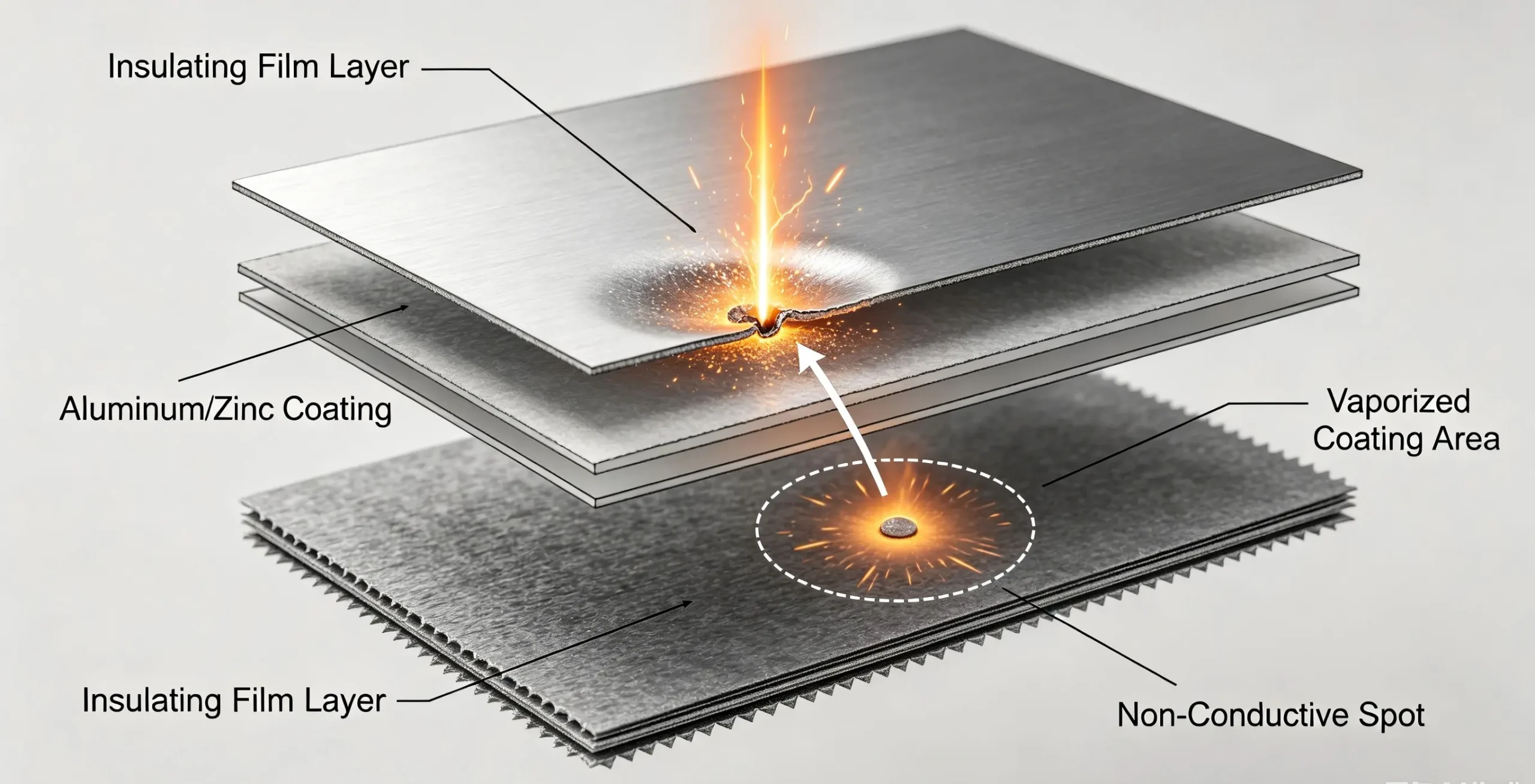
Self-healing technology uses an extremely thin layer of vaporized aluminum or zinc deposited directly onto the plastic insulating film. If a small voltage spike punctures the film, the metal coating surrounding the puncture point instantly vaporizes from the high localized heat, clearing the short circuit and allowing the unit to continue operating normally.
While this prevents an immediate line-to-line short circuit, it is not an all-inclusive protection mechanism. Each self-healing event removes a tiny fraction of the active metalized surface area, causing a gradual drop in total capacity. If the unit experiences frequent overvoltages or high harmonic current distortion, the self-healing cycle will repeat too often, quickly reducing the total capacitance below useful operational limits.